Interlock mechanism for lateral file cabinets

Active Publication Date: 2006-11-30
KNAPE & VOGT MFG
View PDF6 Cites 41 Cited by
  • Summary
  • Abstract
  • Description
  • Claims
  • Application Information

AI Technical Summary

Benefits of technology

[0019] The various aspect of the present invention provides an interlock and lock system that is versatile, resistant to high forces, and easily installed. These and other ben

Problems solved by technology

One disadvantage is the difficulty of changing the drawer configurations within a cabinet.
In the past, such reconfiguring of the drawers in a cabinet has been a difficult task because the interlocking and/or locking system for the drawers could not easily be adjusted to match the newly configured filing cabinet.
Not only does this add additional cost to the process of reconfiguring the cabinet, it complicates the reconfiguring process by requiring new parts of precise dimensions to be ordered.
Finding these precisely dimensioned parts may involve extensive searching and/or measuring, especially where the manufacturer of the rods is not the same entity that produced the new drawers being installed, or the manufacturer of the rods has ceased producing the parts, or has gone out of business.
Another difficulty with systems like that disclosed in the Sawatzky patent is the precise manufacturi

Method used


Image

  • Interlock mechanism for lateral file cabinets
  • Interlock mechanism for lateral file cabinets
  • Interlock mechanism for lateral file cabinets

Examples


first embodiment

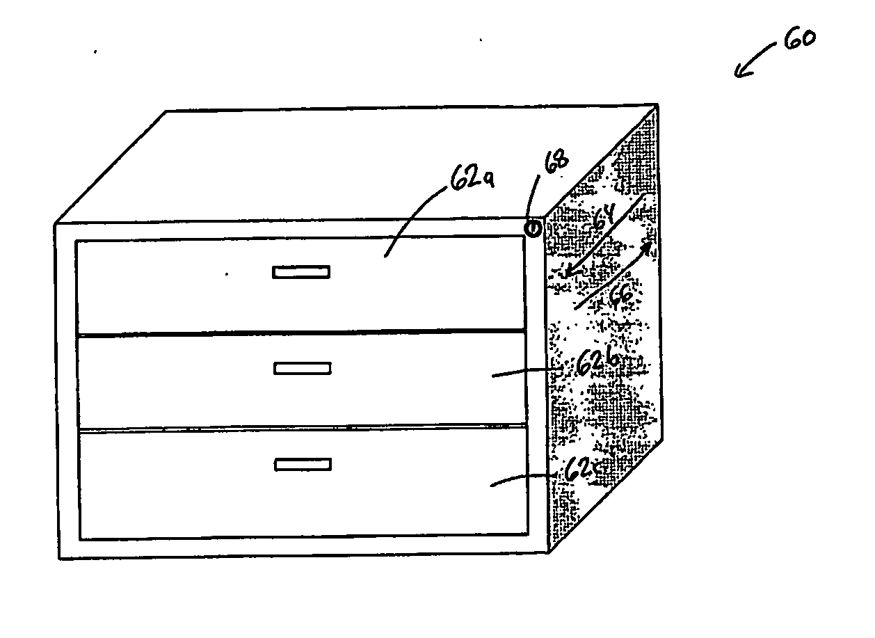
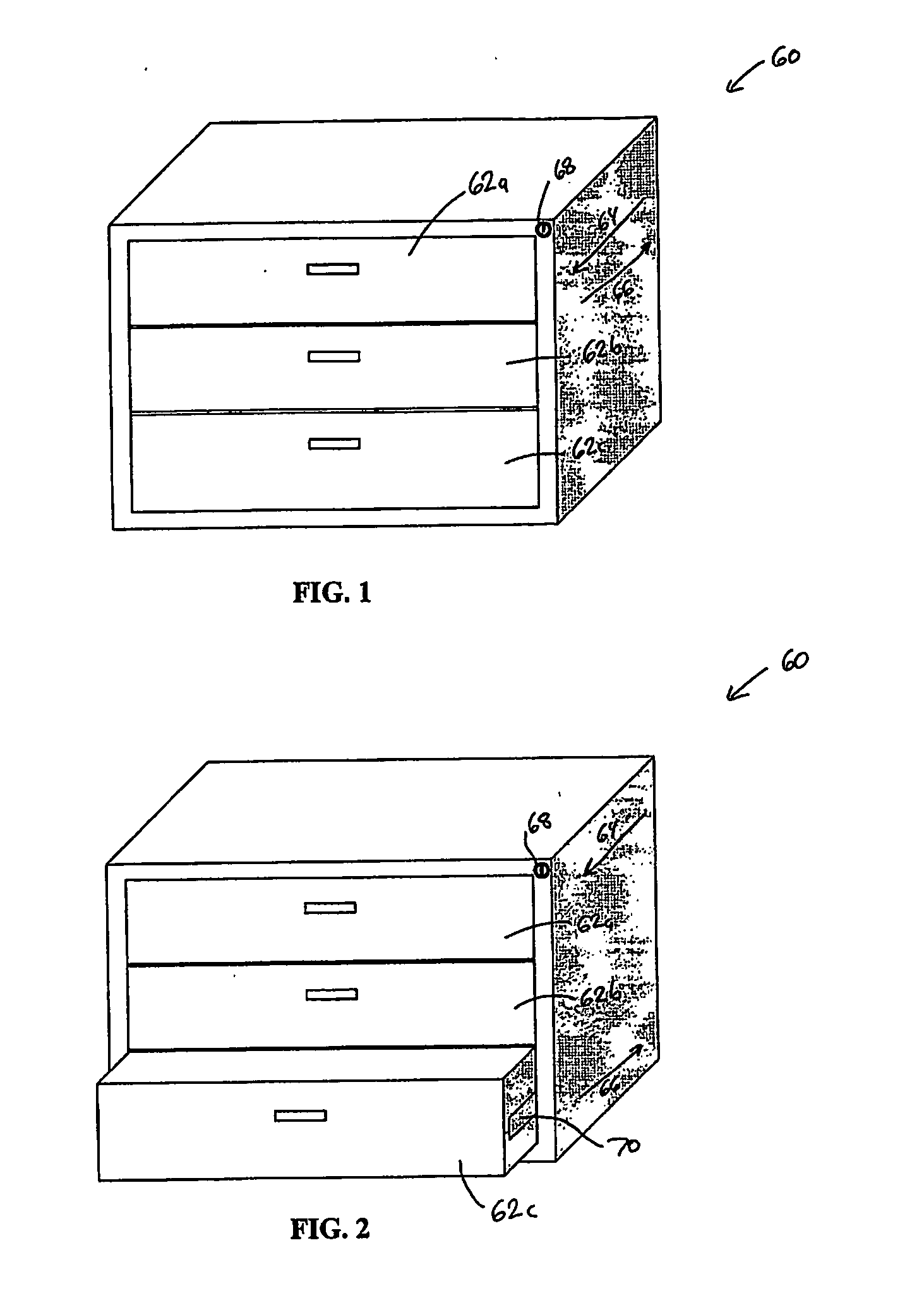
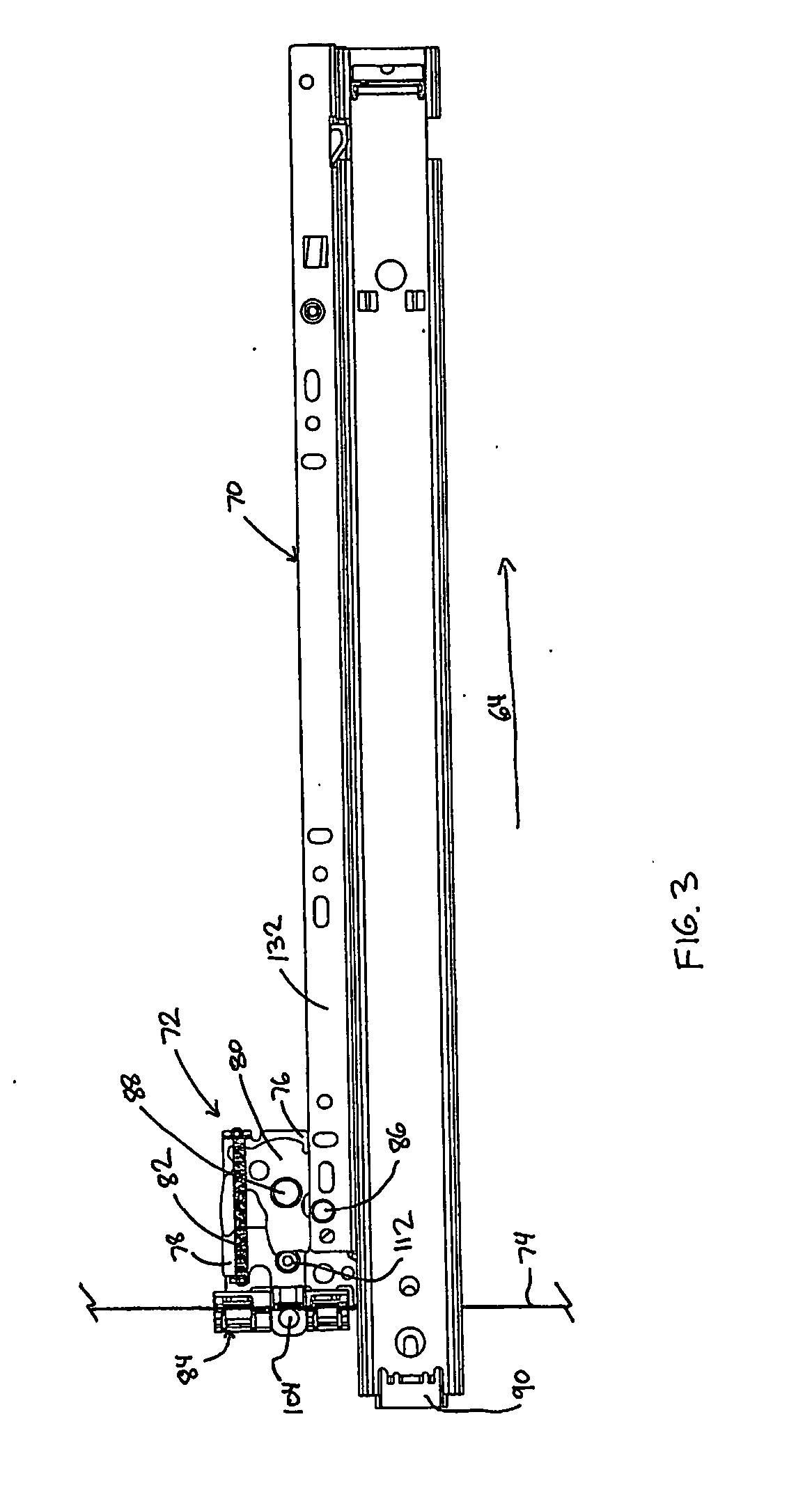
[0083] An interlock 72 according to the present invention is depicted in FIG. 3. Interlock 72 is attached to a drawer slide 70. Interlock 72 is operatively coupled to a cable 74 that runs vertically inside of cabinet 60. In general, interlock 72 operates according to the tension in cable 74. Specifically, cable 74 has two different basic levels of tension. When no drawers are opened and the lock is not activated, cable 74 has a first amount of tension in it. When a single drawer is opened, interlock 72 takes up the slack in cable 74 and creates a second level of tension in cable 74. With the second level of tension, the slack in cable 74 is reduced to such a small level that no other drawers in the cabinet 60 can be opened. When the open drawer is closed, the slack in the cable 74 returns and any other single drawer may thereafter be opened. If a lock is included with the cabinet 60, the lock is adapted to alter the tension in cable 74. When in the locked position, the lock removes ...

second embodiment

[0102] An interlock 72′ according to the present invention is depicted, either partially or wholly, in FIGS. 28-50. Interlock 72′, like interlock 72, is adapted to be attached directly to a drawer slide 70′. While both interlocks 72 and 72′ are depicted attached to the back ends of drawer slides 70 and 70′, it will be appreciated that they can be attached to the drawer slides at any desirable location along the drawer slides' length. Interlock 72′ operates in conjunction with a cable 74 in a similar manner that interlock 72 operates. Specifically, interlock 72′ allows only a single drawer to be open at a given time. If a lock is included in the cabinet, the lock is in communication with cable 74 and can change the amount of slack in cable 74. If the lock is activated, cable 74 has little or no slack, and none of the drawers may be opened. Interlock 72′ differs from interlock 72 in that a small portion of the pulling force exerted on a drawer in first direction 64 is transmitted to c...


PUM


Abstract

The invention relates to interlocks for file cabinets and the like which generally prevent more than one drawer from being opened at a given time. The interlocks include a cable which is changeable from a slack condition to a taut condition. In the taut condition, the interlocks prevent the associated drawer from being opened. In the slack condition, the interlock allows the associated drawer to be opened. The interlocks may be used in conjunction with a lock that selectively changes the tension in the cable from a slack condition to a taut condition and vise versa. The interlocks may be constructed to exert a tension on a cable that is independent of the pulling force exerted on a locked drawer. Alternatively, the interlocks may be constructed to exert a force on the cable that is a small fraction of the pulling force exerted on a locked drawer.

Description

BACKGROUND OF THE INVENTION [0001] The present invention relates to filing cabinets, and more particularly to mechanisms adapted to prevent one or more of the drawers in the filing cabinet from being opened. [0002] It has been known in the past to include interlock mechanisms on filing cabinets that prevent more than one drawer in the cabinet from being opened at a single time. These interlock mechanisms are generally provided as safety features that are intended to prevent the filing cabinet from accidentally falling over, a condition that may be more likely to occur when more than one drawer in the cabinet is open. By being able to open only a single drawer at a given time, the ability to change the weight distribution of the cabinet and its contents is reduced, thereby diminishing the likelihood that the cabinet will fall over. [0003] In addition to such interlocks, past filing cabinets have also included locks that prevent any drawers from being opened when the lock is moved to ...

Claims


Application Information

Patent Timeline
IPC IPC(8): E05B65/46E05B65/466
CPCE05B65/466
Inventor HOFFMAN, KEITH A.
Owner KNAPE & VOGT MFG
Why Eureka
Try Eureka