RFID characterization method

a technology of characterization method and rfid tag, which is applied in the direction of signalling system, alarm, instruments, etc., can solve the problems of limited ability to program and read rfid tags used in thermal printer labels, and become more difficult to interrogate tags quickly and efficiently

Inactive Publication Date: 2007-01-18
PRINTRONIX INCORPORATED
View PDF1 Cites 12 Cited by
  • Summary
  • Abstract
  • Description
  • Claims
  • Application Information

AI Technical Summary

Benefits of technology

[0008] According to one embodiment of the present invention, an RFID reader or encoder is set at its lowest RF power level for interrogation. The RFID tag is placed in a fixed position relative to the antenna. The RFID tag is then interrogated. If the interrogation was not successful, the RF power is increased and the tag is interrogated again. Once the RFID tag has been interrogated successfully, the RF power is recorded and the tag is moved forward a nominal distance, e.g., 0.1 inches. The RFID power is then set to the lowest level again and interrogation continues until a minimum RF power for a successful interrogation is obtained. This process continues until a write / read profile is created as the RFID tag is moved through the printer. Using the profile (in raw data or graphical format), the performance of the particular RFID tag / label within the printer system can be determined, which allows various optimization or performance improvements, such as tag placement within a label, antenna design, and interrogation parameters for a particular type of RFID tag or label. The data / graph could be uploaded to the host for later processing or printed out directly on the labels being profiled.

Problems solved by technology

Furthermore, the capabilities of programming and reading RFID tags used in thermal printer labels is limited, due in part, to the mechanical profile of the printer, which may cause performance issues with radio frequency signals associated with RFID technology, and to the proximity of multiple tags coupled with the need to address (program) only one tag at a time.
However, with an ever-increasing number of different antennas, tags, readers, and encoders, it is becoming more difficult to interrogate tags quickly and efficiently.

Method used


Image

  • RFID characterization method
  • RFID characterization method
  • RFID characterization method

Examples


Embodiment Construction

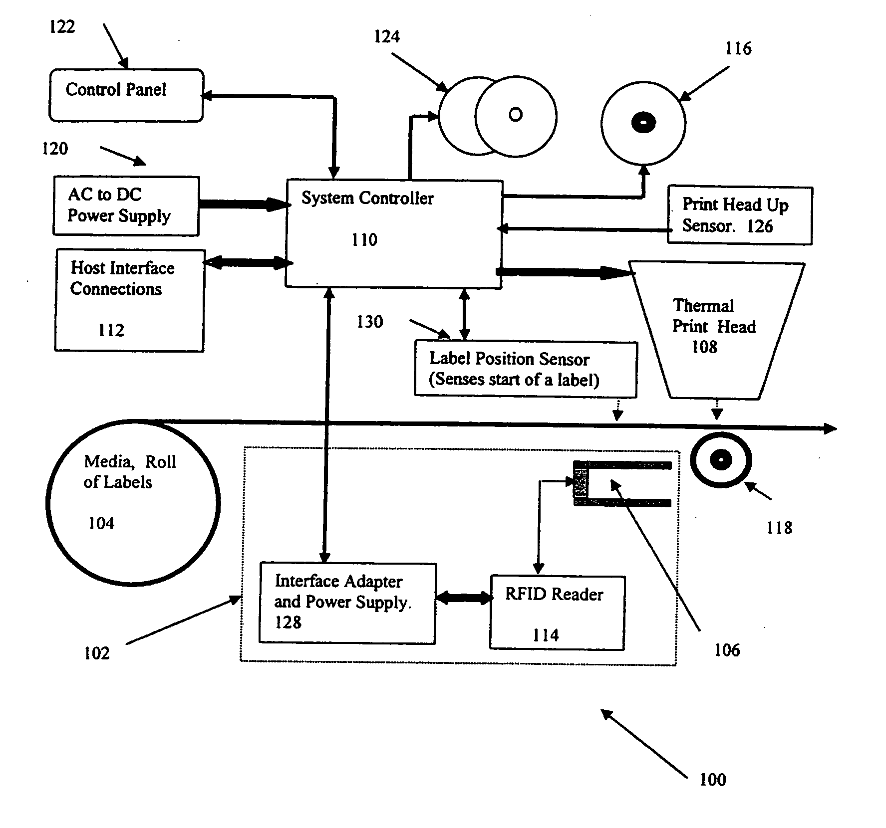
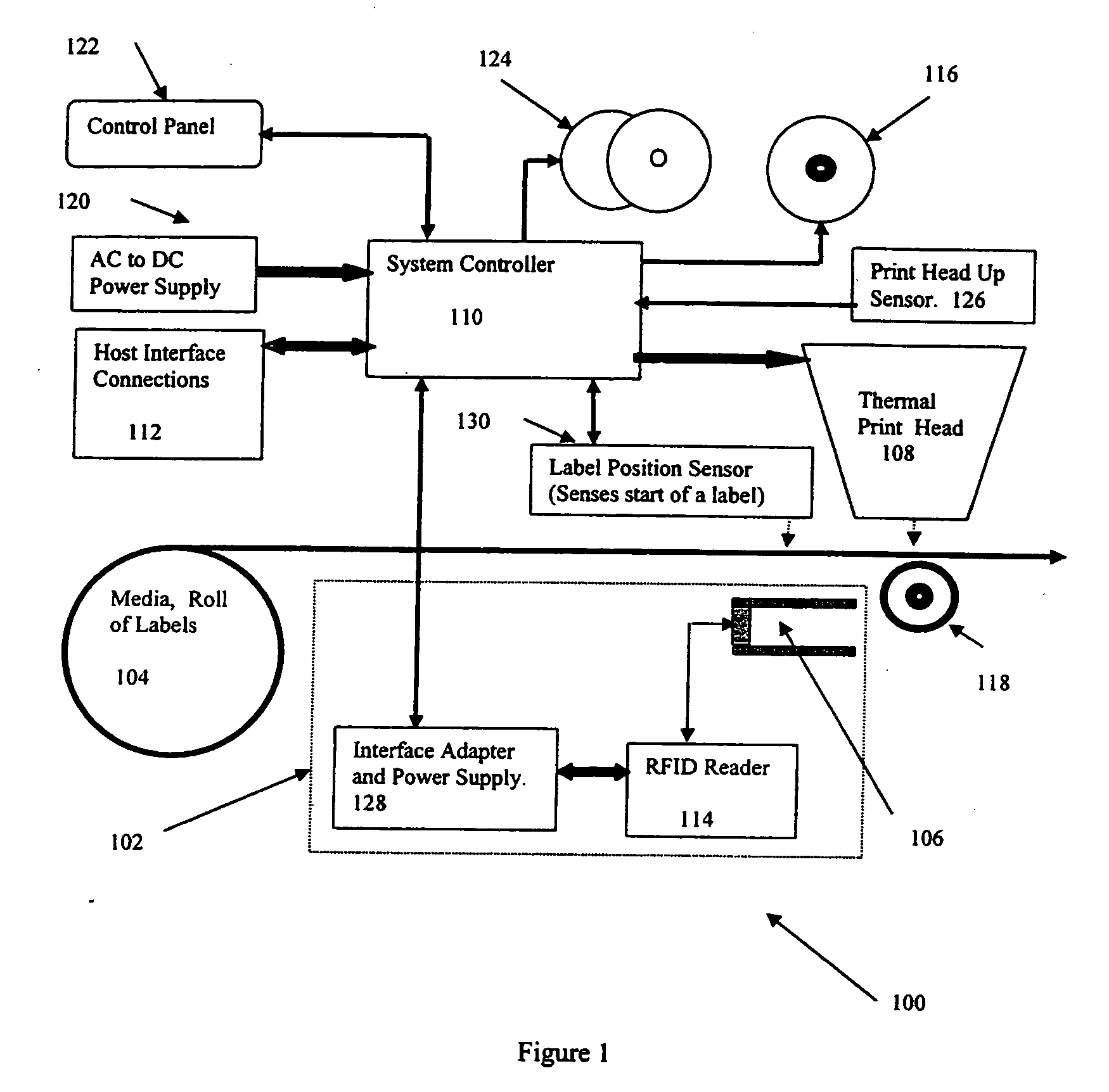
[0016]FIG. 1 shows a block diagram of a printer system 100 with a radio frequency identification (RFID) reader subsystem 102 that can be used to implement one method of the present invention. Printer system 100 also includes a roll 104 of labels or media, where an RFID tag is embedded in each label. In other embodiments, the roll of labels can be replaced by a short strip of RFID labels, sufficient to perform a profile / RF characterization, as will be discussed below. RFID tags are conventional passive tags available from a multitude of manufactures. One such manufacturer is Alien Technology Corporation of Morgan Hill, Calif. Labels from roll 104 are fed over an RFID antenna 106, programmed, and printed by a thermal print head 108. A host computer 112 coupled to a system controller 110 that is in turn coupled to RFID reader subsystem 102, which includes antenna 106, allows the RFID tag on each label to be written to, read, and verified. The resulting label then has both a printed med...


PUM


Abstract

An RFID system, such as an RFID printer system, is used to create an RFID performance profile by interrogating an RFID tag at a first position starting at a minimum RF power and increasing the RF power until a successful interrogation is obtained. The RFID tag is then moved forward into a next position and the interrogation process is repeated, starting at the minimum RF power. The process continues until the RFID tag is out of interrogation range even at a maximum RF power or some other user-defined stop point. The power level and position are stored at each position of the RFID tag during this process. The data is compiled to create a profile of the RF performance, which can then be used in a variety of ways to improve system performance.

Description

BACKGROUND [0001] 1. Field of the Invention [0002] The present invention relates generally to methods of operating an RFID system, and more particularly to methods of encoding and reading RFID tags. [0003] 2. Related Art [0004] The main function of printers is to deliver printed images. One example of printed images is bar code labels that are used in the supply chain for efficient processing and handling of goods in transit. Recent developments in technology allow Radio Frequency Identification (RFID) inlays (passive or active transponders) to be embedded in the bar code label. The transponder provides an electronic means of storing information and a non-contact, non-line of sight method for reading the stored data. [0005] One common method for encoding RFID bar code labels is to use a printer / encoder. In such a system, an RFID encoder (sometimes called a reader) and antenna are integrated in the printer to enable both printing of the label information and programming of the RFID t...

Claims


Application Information

Patent Timeline
Patent Type & Authority Applications(United States)
IPC IPC(8): H04Q5/22G08B5/22
CPCG06K19/0723
Inventor EDWARDS, ANDREW W.SCHUMAKER, RICHARD E.HARKINS, JAMES P.GIBBS, DUANE C.BLANTON, RICKY D.
Owner PRINTRONIX INCORPORATED
Why Eureka
Try Eureka