Dynamic bias for RF power amplifiers

Inactive Publication Date: 2006-03-07
INTERDIGITAL TECH CORP
View PDF15 Cites 16 Cited by
  • Summary
  • Abstract
  • Description
  • Claims
  • Application Information

AI Technical Summary

Benefits of technology

[0016]The present invention is a subscriber unit and method that dynamically adjusts the operating bias of an RF amplifier of the subscriber unit's transmitter in response to a transmit power control (TPC) signal. The invention provides high-efficiency RF power amplification for ap

Problems solved by technology

When a subscriber unit or a base station is receiving a specific signal, all other subchannels or subscriber units' signals appear as noise.
Therefore, increasing the power level of one subscriber unit's signal increases the noise presented to all other subscriber units.
Large transient peaks are undesirable.
This results in increased out-of-band emissions and reduced amplifier efficiency.
This

Method used


Image

  • Dynamic bias for RF power amplifiers
  • Dynamic bias for RF power amplifiers
  • Dynamic bias for RF power amplifiers

Examples


Example

[0024]The embodiments will be described with reference to the drawing figures where like numerals represent like elements throughout.

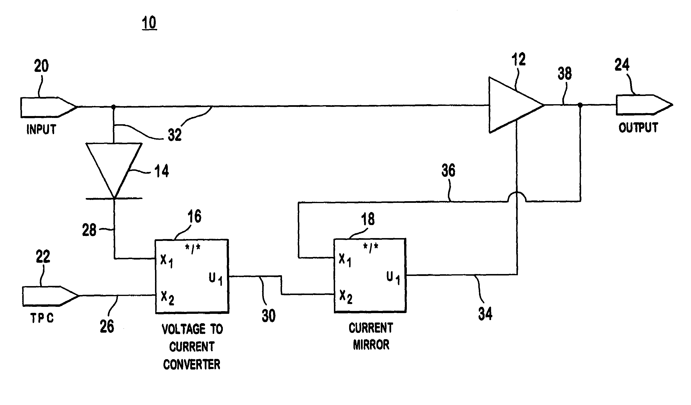
[0025]Shown in FIG. 4 is the dynamic bias amplification system 10 of the present invention incorporated within a subscriber unit. However, those of skill in the art should realize that this may also be incorporated as part of a base station. The system 10 comprises a communication signal input 20, an amplifier 12, a detector 14, a power control signal input 22, a voltage to current converter 16, a current mirror 18 and an output 24. For convenience in describing the present invention, reference is made to a wireless communication system using a TPC signal. However, those of skill in the art would recognize that the present invention may be utilized with any type of communication system utilizing a power control signal.

[0026]The communication signal input 20 provides an input wireless communication signal 32 ready for transmission. This input wireless c...


PUM


Abstract

A subscriber unit and method for wireless communication that dynamically adjusts RF amplifier operating bias for the subscriber unit's transmitter in response to a power control signal. The invention provides high-efficiency RF power amplification for applications where the available power source is limited. The invention uses a power control signal resident in wireless communication system architectures with a detector and voltage to current converter to arrive at a dynamic amplifier operating bias.

Description

CROSS REFERENCE TO RELATED APPLICATION(S)[0001]This application is a continuation of U.S. patent application Ser. No. 09 / 773,857, filed on Feb. 1, 2001, now Pat. No. 6,684,064 and claims priority from Provisional Patent Application Ser. No. 60 / 192,528, filed on Mar. 28, 2000.FIELD OF INVENTION[0002]The present invention relates generally to wireless digital communication systems. More specifically, the invention relates to a system and method for dynamically biasing a radio frequency (RF) power amplifier used for transmitting wireless communications.BACKGROUND[0003]A digital communication system typically transmits information or data using a continuous frequency carrier with modulation techniques that vary its amplitude, frequency or phase. After modulation, the signal is amplified and transmitted over a communication medium.[0004]A multiple-access communication system allows a plurality of subscriber units to access the same communication medium to transmit or receive information....

Claims


Application Information

Patent Timeline
IPC IPC(8): H04B1/04H03F3/24H03F1/02H03F1/06H03F1/30H03G3/30H04B7/005
CPCH03F1/0205H03F1/0233H03F1/0261H03F1/0266H03F1/30H03G3/3042H03G3/3084H04W52/52H03F1/0222Y02B60/50H03F2200/451H03F2200/474H04B2001/0416H04B2001/045H04W52/08H03F1/02H03F3/24H04B7/005
Inventor KAZAKEVICH, LEONIDCABROL, PATRICK
Owner INTERDIGITAL TECH CORP
Why Eureka
Try Eureka