GPS Based Situational Awareness and Identification System and Method

a situational awareness and identification system technology, applied in the field of security systems, can solve problems such as confusion between different perspectives, personal vs. professional, and information does the individual little good, and achieve the effects of reducing the number of people in the system, and improving the quality of li

Active Publication Date: 2007-01-25
SPATIAL REALITY LLC
View PDF18 Cites 38 Cited by
  • Summary
  • Abstract
  • Description
  • Claims
  • Application Information

AI Technical Summary

Benefits of technology

[0013] A spectator at the 3rd turn with “my view” selected can see the perspective of the rendering on the portable device to match his own visual observation—i.e. his location including elevation. This adds to a much greater enjoyment of the situation because visual data is added to the display which matches his visual observation. Importantly, the spectator can not only switch views, but can also tilt or pan the perspective or observation point or zoom. That is, from “my view” the spectator might rotate a toggle up incrementally up (or down) from the horizontal view from the spectator's location of the car positions to a vertical view of the situation. Preferably, the toggle would also allow left / right pan functions at any time.

Problems solved by technology

Such divergent perspectives—announcer versus personal—can be confusing.
What is lacking in security applications, including the military, is an integrated GPS system for an individual user to gain situational awareness.
That is, while an infantry soldier or security agent might wear a GPS tracking device that transmits his position, this information does the individual little good.
While one limitation to the applicability of the present invention to security situations is the ability to determine the position of all participants, those limitations are becoming less meaningful as technology progresses.

Method used


Image

  • GPS Based Situational Awareness and Identification System and Method
  • GPS Based Situational Awareness and Identification System and Method
  • GPS Based Situational Awareness and Identification System and Method

Examples


Embodiment Construction

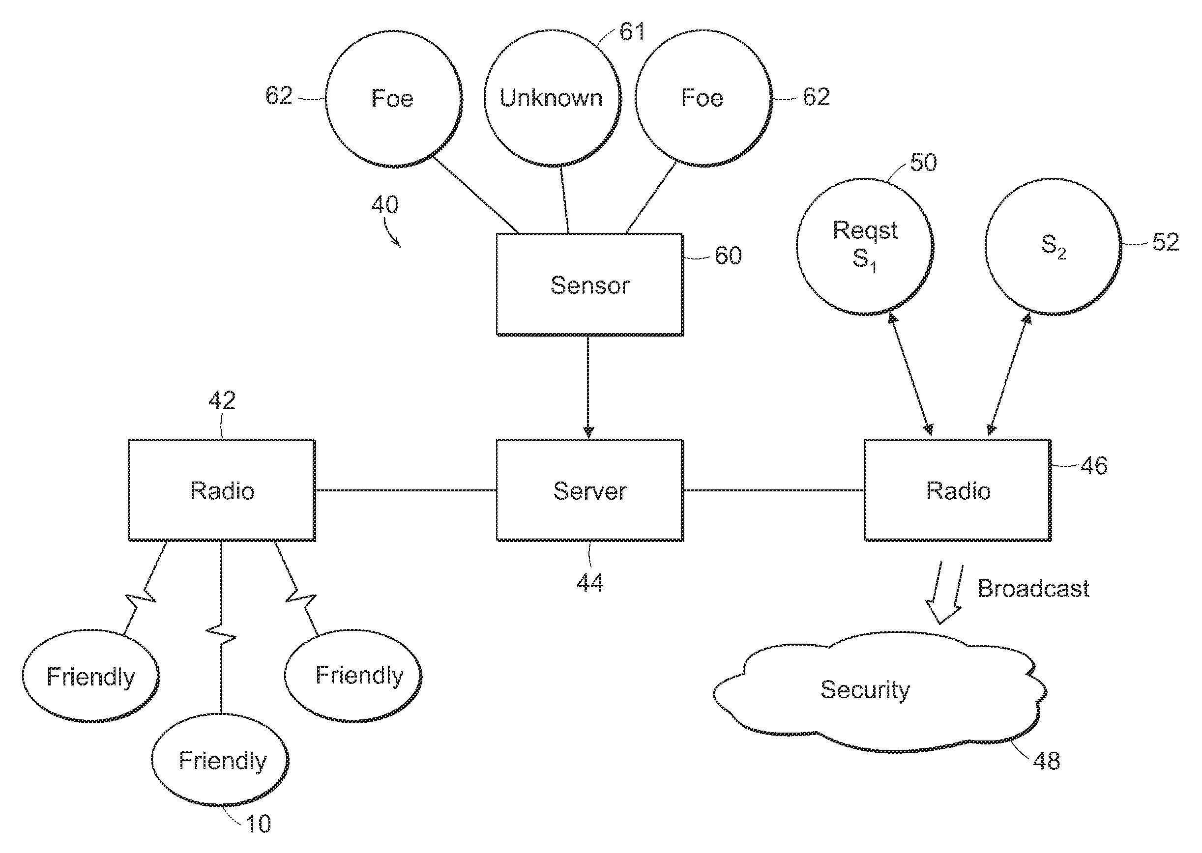
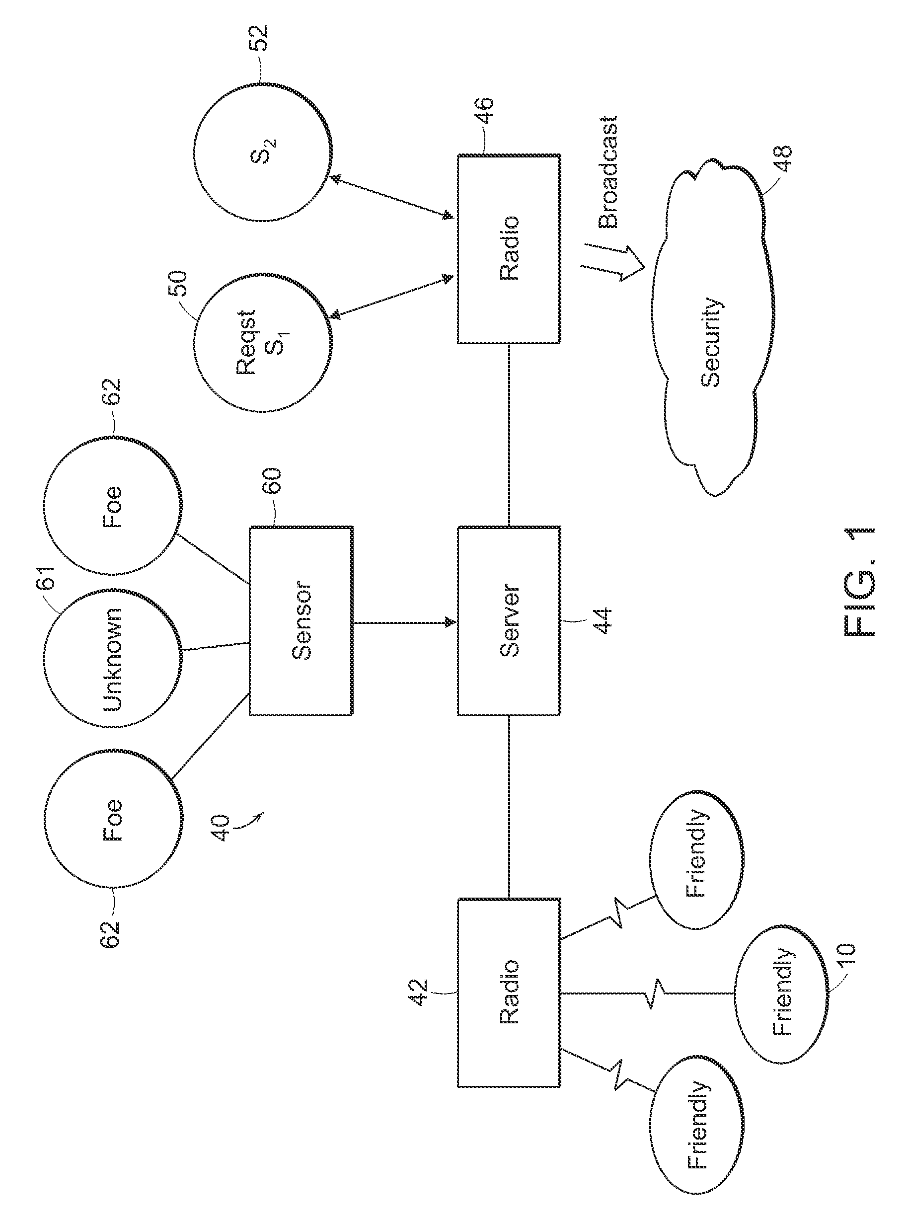
[0030] In FIG. 1, a depiction of the network 40 is shown. The friendlies 10 communicate with a radio base station 42 preferably using spread spectrum radio (encrypted or secured if desired). A spread spectrum radio such as made by Freewave Technologies of Boulder, Colo. is a preferred choice (e.g. a 900 MHz board level module). The server 44 stores the position data of each friendly 10 communicated to the base station 42, and other pertinent data such as car sensor data, etc. Ideally, the server 44 can also digitally store the voice communications of interest and images of various scenes of possible interest, i.e., other friendlies. Of course, the server 44 can store command and control messages as well for delivery to friendlies 10. The server 44 can also be used for authentication of portable devices 20 and enable selectable requests from friendlies (i.e. ammunition or food for delivery). In some applications, the participants might broadcast location information directly to other...


PUM


Abstract

A system and method for observing a security event which shares the position of a number of friendly participants with other participants. Preferably, the position of unknown participants or foes is also displayed to friendly participants. The views are selectable by friendly participants on, for example, a handheld device, to include a view from the participant's position, zoom, pan, and tilt views, or views of another friendly or from another location, giving increased situational awareness. Other information can be shared among friendly participants, including status and directions.

Description

PRIORITY CLAIM [0001] This application claims priority to U.S. Provisional Application No. 60 / 699,205 filed Jul. 14, 2005 and claims the benefit under 35 U.S.C. § 120 to concurrently-filed application entitled “GPS Based Spectator and Participant Sport System and Method.”BACKGROUND [0002] 1. Field of the Invention [0003] This invention relates generally to security systems and, in particular, to an individual system which depicts other people and objects. In a preferred form, the user can change the depiction including viewing potential foes from a number of angles, locations, and magnitudes. [0004] 2. Description of Related Art [0005] GPS systems have been used in sports by participants in contests where position, location and distance to features are important. For example, U.S. Pat. No. 5,364,093 describes a GPS system and method for allowing a golfer to tell distance to a hole or other feature, and permits the course to track and manage golfers on the course. NASCAR with Sportsl...

Claims


Application Information

Patent Timeline
Patent Type & Authority Applications(United States)
IPC IPC(8): G01S13/78
CPCA63B24/0021A63B71/0605A63B2024/0025A63B2220/836A63B2225/50A63F13/12G02B27/017A63F2300/69A63F2300/8017G01S5/0009G01S5/0027G01S19/42A63F2300/406A63F13/65A63F13/216A63B71/06
Inventor HUSTON, CHARLES D.
Owner SPATIAL REALITY LLC
Why Eureka
Try Eureka