Bottling system

a technology of container and bottle, applied in the field of container system, can solve the problems of inconvenient and normal processing time, and achieve the effect of cost-effectiveness

Active Publication Date: 2017-06-08
JETSTREAM WINE TECH INC
View PDF3 Cites 3 Cited by
  • Summary
  • Abstract
  • Description
  • Claims
  • Application Information

AI Technical Summary

Benefits of technology

[0022]Made from Affinity Plastomer, an FDA approved material used in artificial corks, the present device will be manufactured in a clean room environment using standard extrusion forming methods. The device is designed to take advantage of cost effect

Problems solved by technology

The process normally takes conside

Method used


Image

  • Bottling system
  • Bottling system
  • Bottling system

Examples


Embodiment Construction

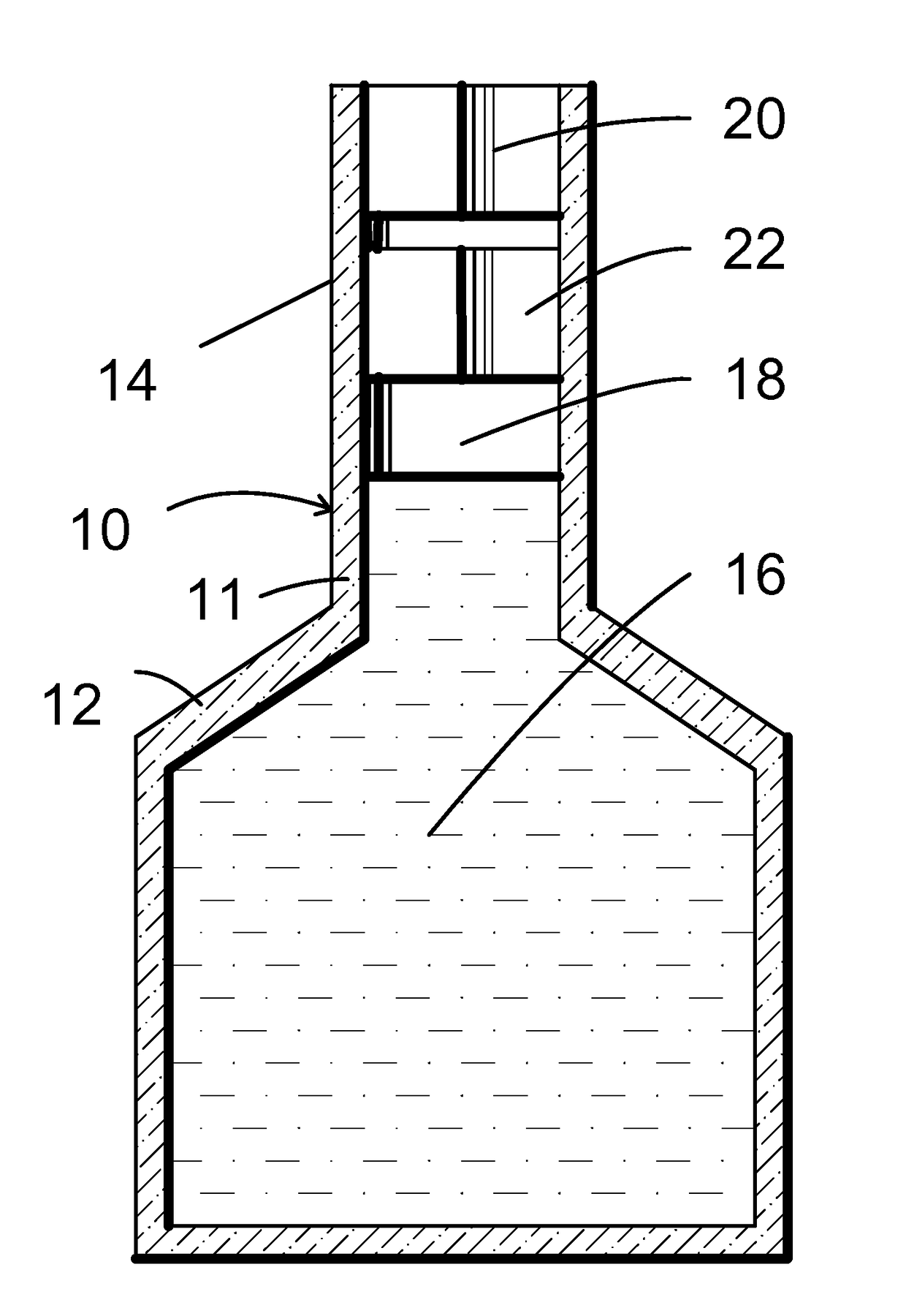
[0034]Referring first to FIG. 1, FIG. 1 is a sectional front elevation view, taken along view 1-1 of FIG. 1A, of a container system for liquids, showing the location of the in-container mixer / aerator in the exit throat of the container. The bottling system, denoted generally by the numeral 10, includes a bottle 11, that includes a hollow body 12 and a neck 14. The body 12 contains a liquid 16, such as wine. The neck 14 surrounds a hollow bore 18 that allows the liquid 16 to exit the bottle 11.

[0035]At the outboard end of the bore 18, is a cork 20 that is removable to allow the liquid 16 to be poured from the bottle 11.

[0036]Inward of the cork is a mixer 22, that includes axial channels 24 that allow liquid to turbulently exit the bore 18, and air to enter the bore 18. The turbulent exit of the liquid 16 enhances the “breathing” of the exiting liquid 16.

[0037]FIG. 1A is a plan view of a container system for liquids shown in FIG. 1.

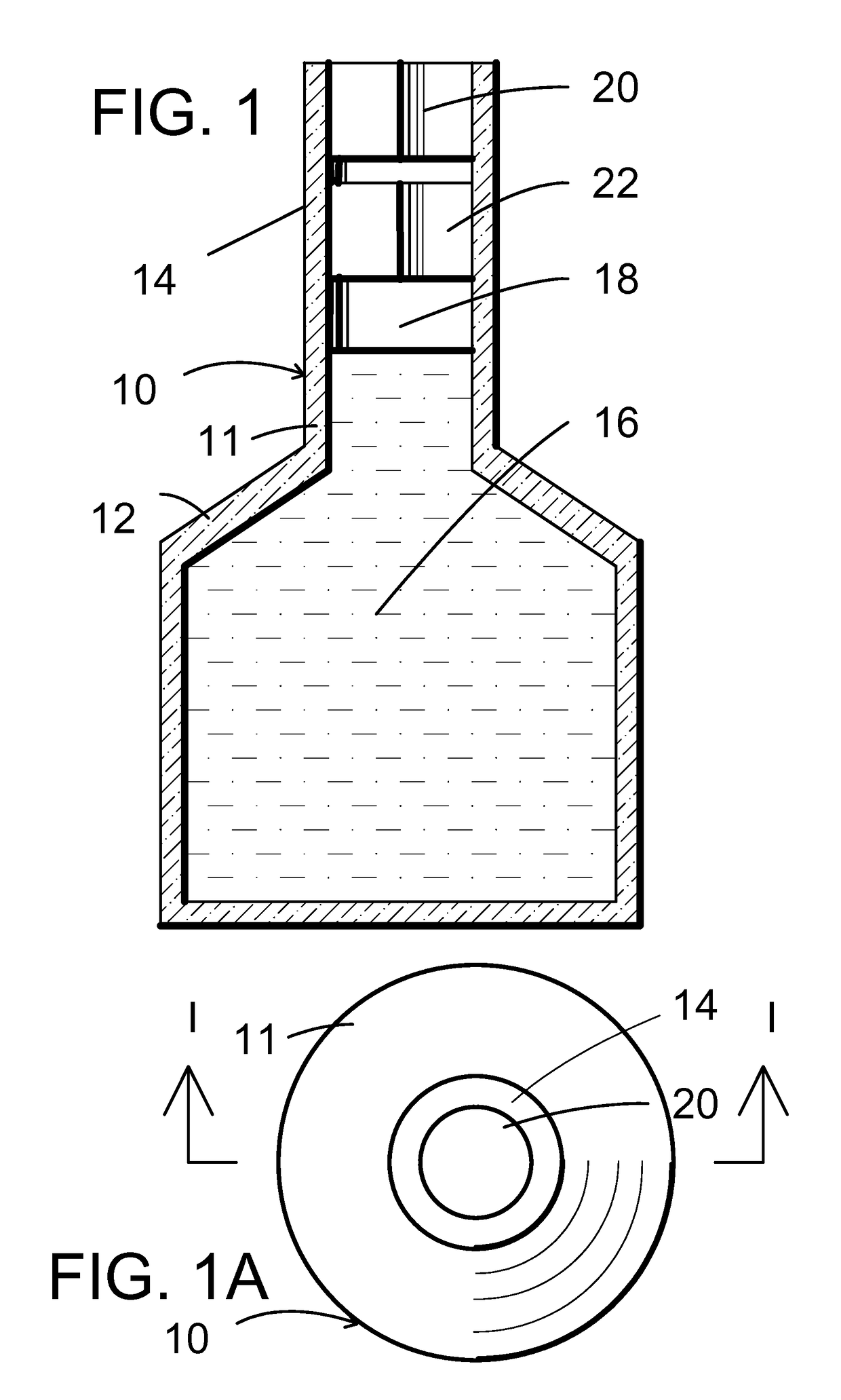
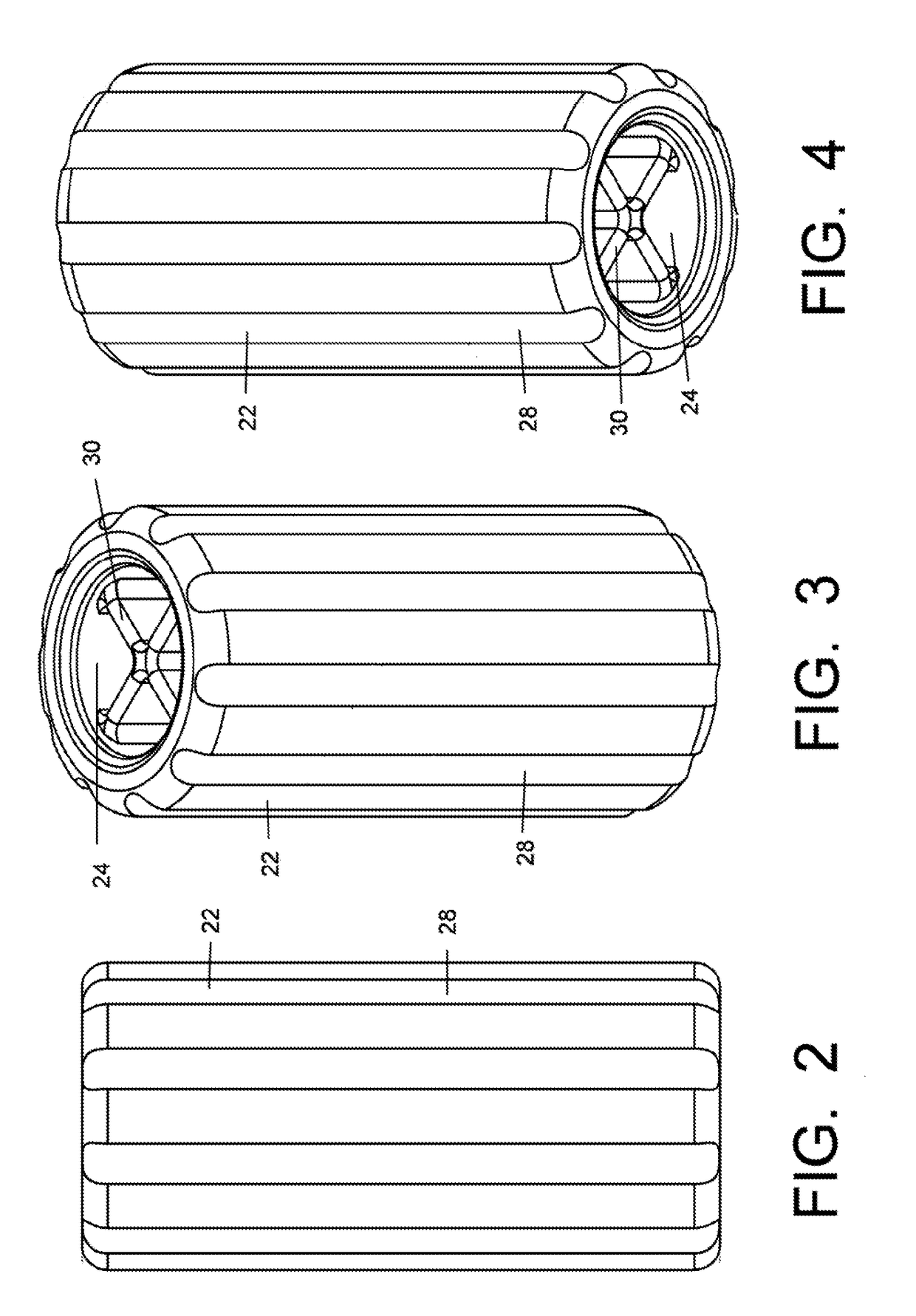
[0038]FIG. 2 is a front elevation view of a mixer emb...


PUM


Abstract

A container system for liquids, including an in-container mixer/aerator in the exit throat of the container. The mixer/aerator is a cylinder, having axial peripheral grooves, and and axial central bore, divided by axial vanes.

Description

CROSS-REFERENCE TO RELATED APPLICATIONS[0001]This application claims priority to U.S. Provisional Patent Application No. 62 / 147,517, filed Apr. 14, 2015, and to U.S. Provisional Patent Application No. 62 / 088,594, filed Dec. 6, 2014, the entireties of which are incorporated by reference herein in their entireties.FIELD OF THE INVENTION[0002]This invention involves an in-container system for enhancing the turbulence and aeration of a liquid in a container.BACKGROUND[0003]Some beverages, such as wine, benefit from “breathing”, the process of removing the beverage from its storage container and exposing the beverage to air and turbulence. The process normally takes considerable time and can be inconvenient. What is needed is a system for making the “breathing” procedure more efficient and convenient.SUMMARY OF THE INVENTION[0004]The invention involves a container system for liquids, comprising a container for a liquid, a throat on the container which allows liquid to be poured form the ...

Claims


Application Information

Patent Timeline
IPC IPC(8): B01F3/04C12G1/00B01F5/06B65D1/02B65D23/04
CPCB01F3/04794B65D1/023B65D23/04B01F2215/0072C12G1/00B01F2003/04872B01F5/0644B01F25/4323B01F25/44161B01F25/44167B01F2101/17B01F23/2361B01F23/237611
Inventor GAETA, CHERYLKMETZ, DAVID G.PELOSI, MICHAEL J.
Owner JETSTREAM WINE TECH INC
Why Eureka
Try Eureka