Laser erosion processes for fiber optic ferrules

a fiber optic ferrule and laser erosion technology, applied in the field of laser erosion can solve the problem of unsuitable endface of fiber optic ferrules

Inactive Publication Date: 2009-02-12
CORNING CABLE SYST LLC
View PDF26 Cites 55 Cited by
  • Summary
  • Abstract
  • Description
  • Claims
  • Application Information

AI Technical Summary

Benefits of technology

[0006]In various embodiments, the present invention provides laser erosion processes for shaping and preparing the end face of a fiber optic ferrule that involve minimal optical fiber tip modification. The laser erosion processes provide for the precise selection of the associated optical fiber protrusion length. As such laser erosion processes typically render the endface of the fiber optic ferrule unsuitable for interferometric measurements due to the very rough, non-reflective surface that results, integral datums may be positioned about the ferrule end face to provide a suitable metrology reference surface. One form of integral datum may include a reference surface recessed within one or more guide pin bores. In embodiments in which laser erosion processes result in core erosion of the optical fibers, masking, the use of oblique laser beam irradiation angles, and / or a clean-up flocking may be included as processing steps. Masking and the use of oblique laser beam irradiation angles eliminate direct laser beam interaction with the optical fiber core. A clean-up flocking step combines the laser erosion processes of the present invention with conventional mechanical processes for shaping and preparing the endfaces of fiber optic ferrules, remedying the preferential core erosion of the optical fibers after the fact.

Problems solved by technology

As such laser erosion processes typically render the endface of the fiber optic ferrule unsuitable for interferometric measurements due to the very rough, non-reflective surface that results, integral datums may be positioned about the ferrule end face to provide a suitable metrology reference surface.

Method used


Image

  • Laser erosion processes for fiber optic ferrules
  • Laser erosion processes for fiber optic ferrules
  • Laser erosion processes for fiber optic ferrules

Examples


Embodiment Construction

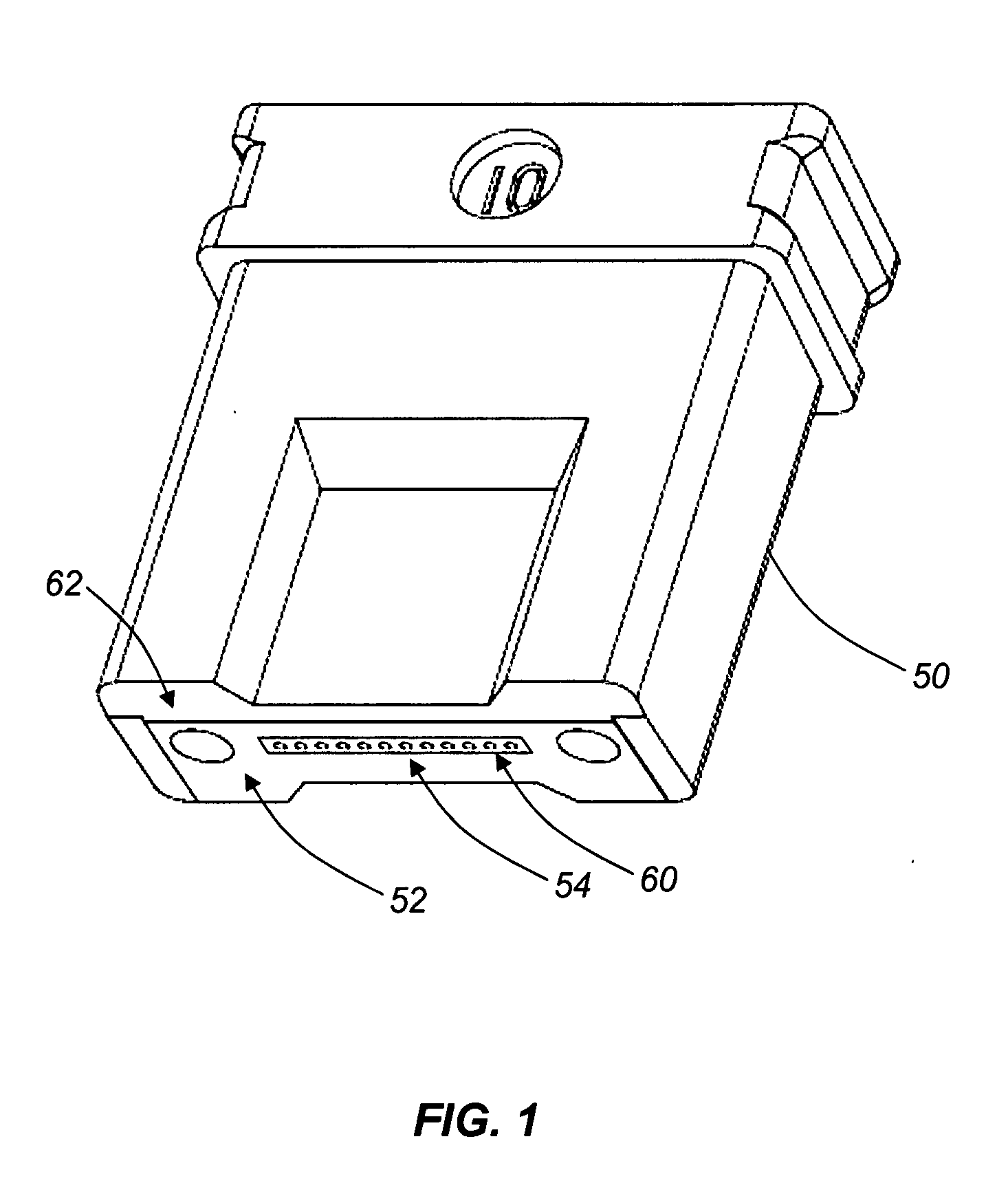
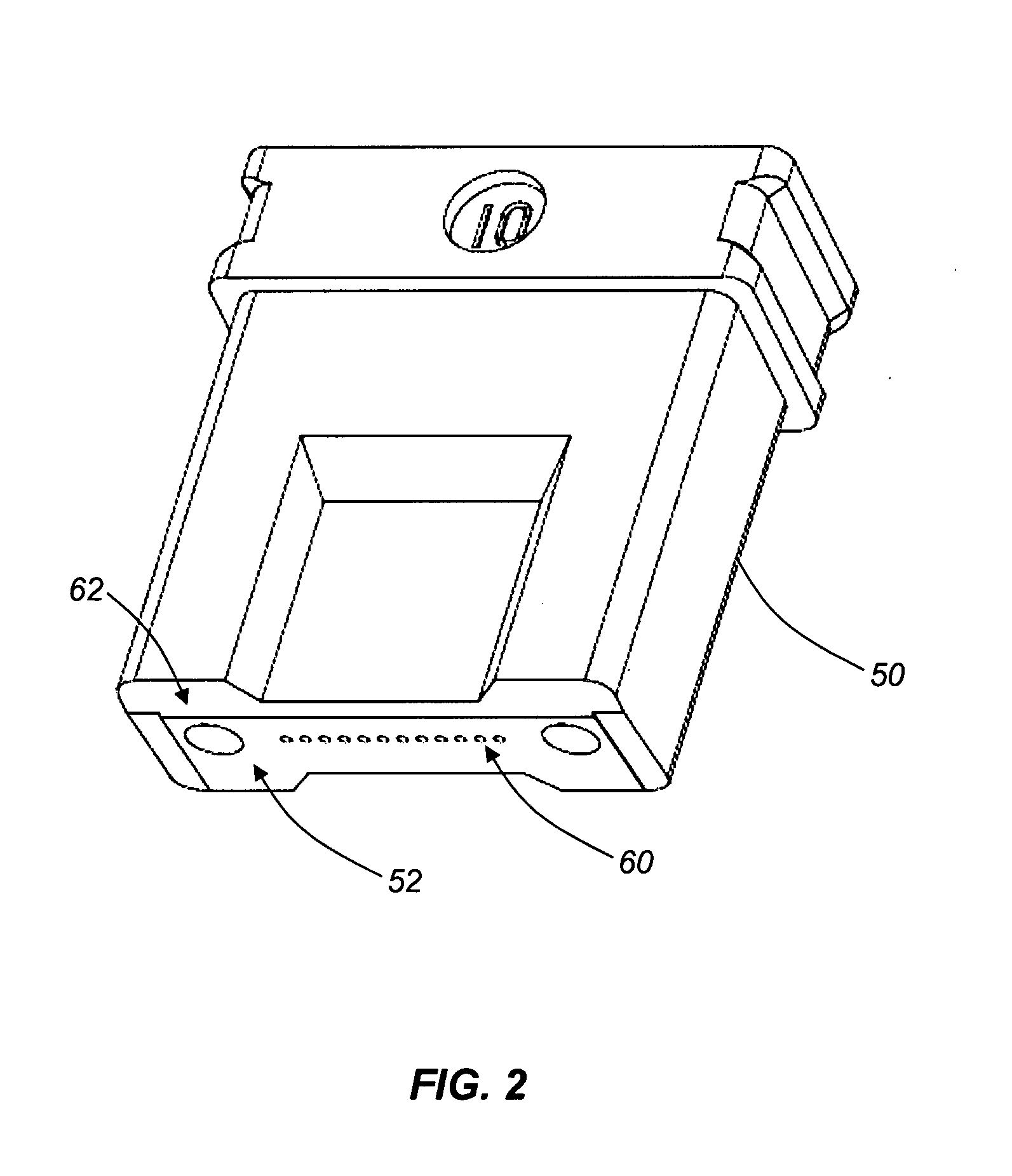
[0014]In various embodiments, the present invention provides laser erosion processes for treating the endface of a fiber optic ferrules that involve minimal optical fiber tip modification, the laser erosion processes providing for the precise selection of the associated optical fiber protrusion lengths and optionally the incorporation of integral datums. As such laser erosion processes typically render the endface of the fiber optic ferrule unsuitable for interferometric measurements due to the very rough, non-reflective surface that results, integral datums may be formed to provide suitable metrology reference surfaces. One form of an integral datum includes a reference surface recessed within the guide pin bores. As such laser erosion processes also typically result in preferential core erosion of the optical fibers, masking, the use of oblique laser beam irradiation angles, and / or a clean-up flocking step are preferred. Masking and the use of oblique laser beam irradiation angles...


PUM

PropertyMeasurementUnit
poweraaaaaaaaaa
poweraaaaaaaaaa
angleaaaaaaaaaa

Abstract

A method for processing fiber optic ferrules, the method comprising: providing a fiber optic ferrule defining an endface portion and a pedestal portion about one or more protruding optical fibers; mechanically polishing the one or more protruding optical fibers substantially flush with the pedestal portion; and non-mechanically eroding the pedestal portion about the one or more protruding optical fibers to a depth of at least the end face portion such that the one or more optical fibers remain protruding from the endface portion. Non-mechanically eroding may include laser erosion or chemical erosion.

Description

BACKGROUND OF THE INVENTION[0001]1. Field of the Invention[0002]The present invention relates generally to the processing of fiber optic ferrules, and more specifically, to erosion processes for removing ferrule material from the ferrule end face about the optical fibers so that the fibers protrude a predetermined distance from the end face.[0003]2. Technical Background of the Invention[0004]Conventional mechanical processes for shaping and preparing the end face of fiber optic ferrules, and providing for the selection of the associated optical fiber protrusion lengths, typically involve inserting and bonding the optical fibers in the fiber optic ferrule such that they have a protrusion length that exceeds a desired final protrusion length, for example, and then cleaving or polishing the optical fibers to the desired protrusion length, with minimal polishing of the endface of the fiber optic ferrule. Most often, these mechanical processes result in the optical fibers being polished ...

Claims


Application Information

Patent Timeline
Patent Type & Authority Applications(United States)
IPC IPC(8): G02B6/36B29D11/00
CPCB29D11/0075G02B6/381G02B6/3885G02B6/3863G02B6/3834
Inventor DANLEY, JEFFREY DEANLUTHER, JAMES PHILLIPKNECHT, DENNIS MICHAELROSSON, JOEL CHRISTOPHER
Owner CORNING CABLE SYST LLC
Why Eureka
Try Eureka