Cord anchor

Inactive Publication Date: 2007-02-01
HUNTER DOUGLAS IND BV
View PDF19 Cites 83 Cited by
  • Summary
  • Abstract
  • Description
  • Claims
  • Application Information

AI Technical Summary

Benefits of technology

[0017] According to a second aspect of the invention, the holder or the clamp, which comprises the plug, includes a channel for receiving the cord. Advantageously, the channel is a U-shaped channel comprising a transverse, generally horizont

Problems solved by technology

However, these anchors are relatively bulky because of the perpendicular openings in their base, needed for their clamping action.
Also in the anchor of DE 29922954U, its clamping action depends upon a u

Method used


Image

  • Cord anchor
  • Cord anchor
  • Cord anchor

Examples


Embodiment Construction

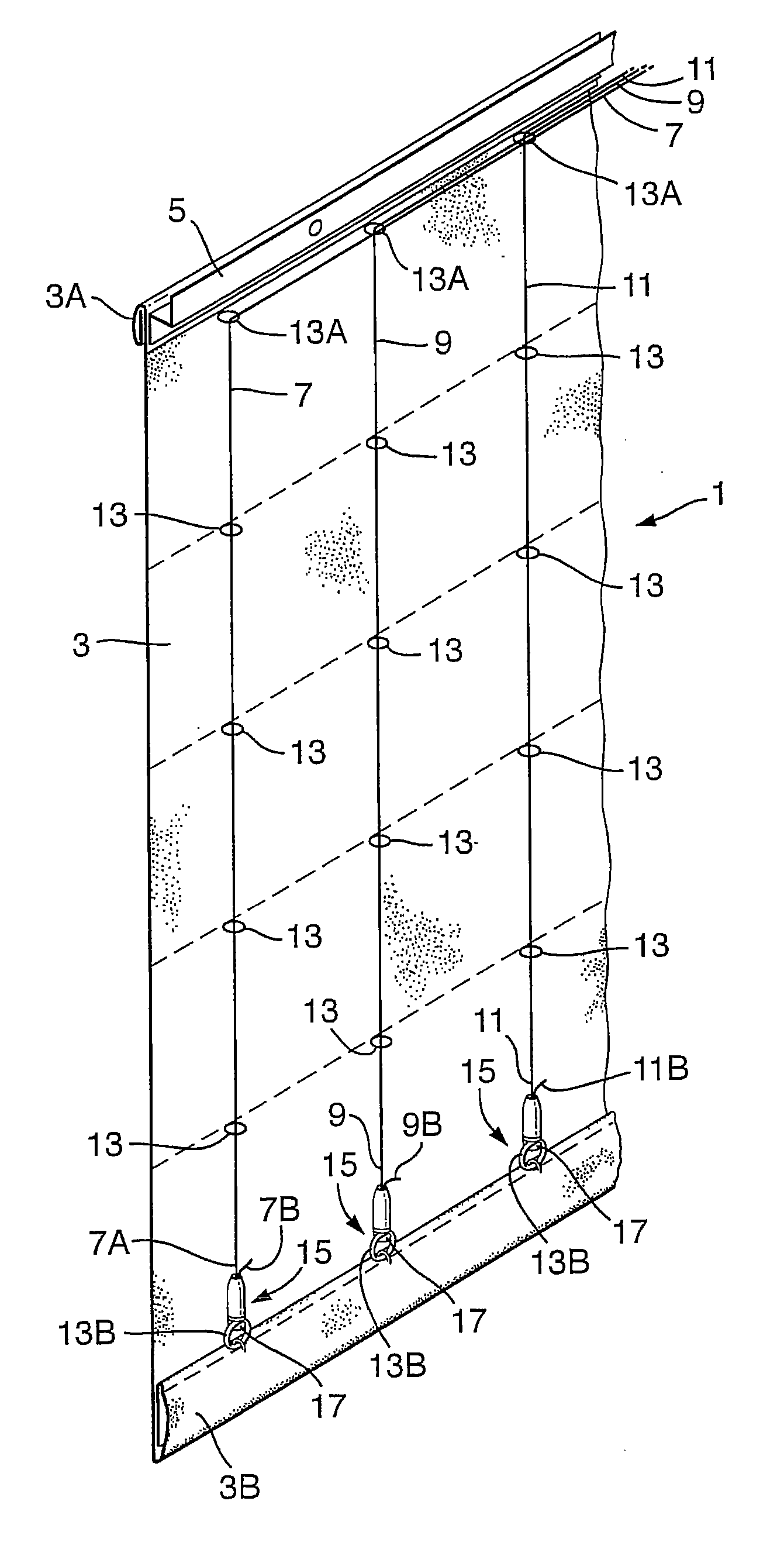
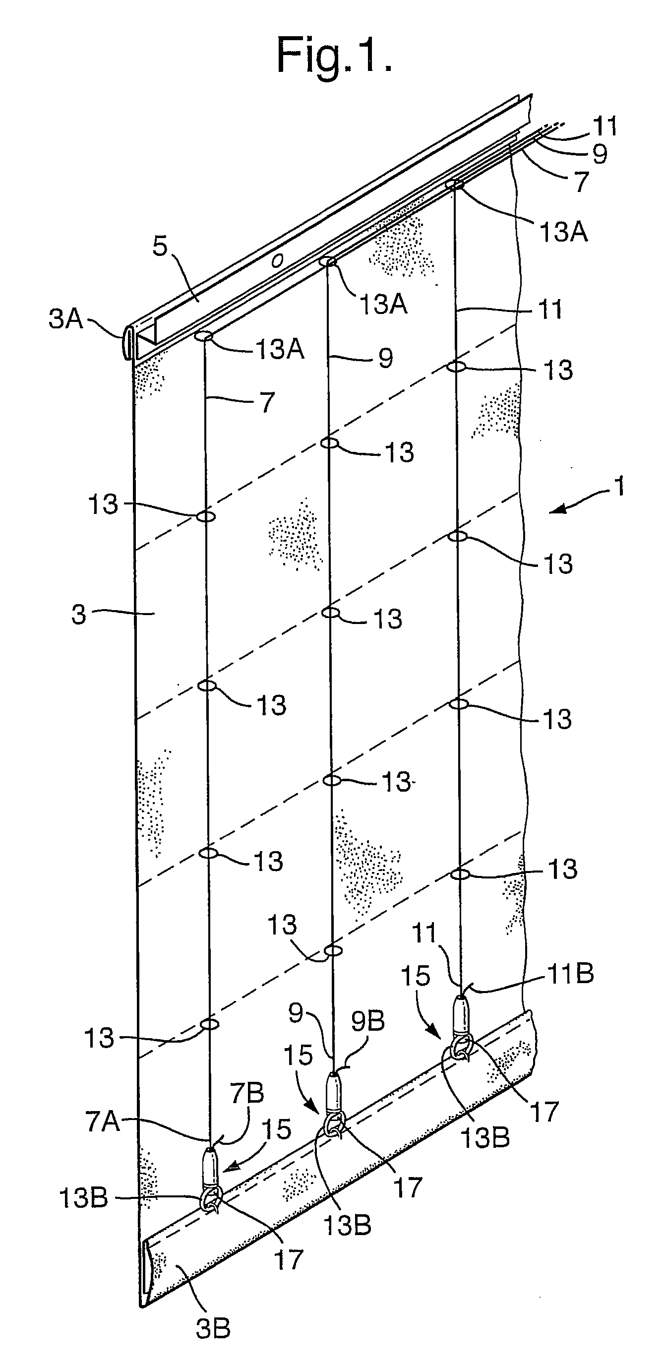
[0027]FIG. 1 shows a roman shade 1 with a fabric panel 3, having a top rim 3A for attachment to a header 5, pull cords 7, 9,11 threaded through parallel, vertically-extending columns of rings 13 on rear of the panel 3. A cord anchor 15 of this invention is on the lower portion 7B, 9B, 11B of each pull cord 7, 9, 11. Each anchor 15 includes a hook 17 for attachment to a bottom ring 13B of each column of rings 13 near a bottom rim 3B of the shade 3.

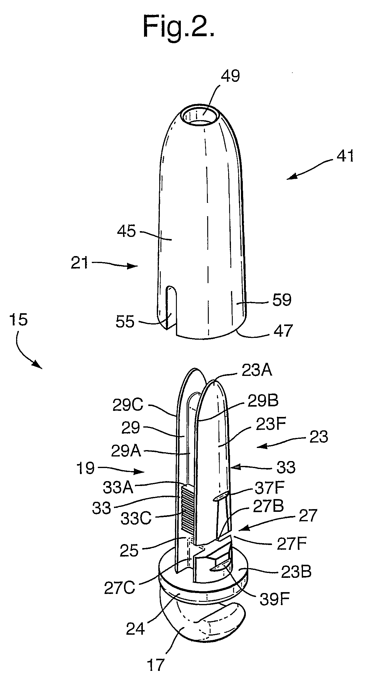
[0028]FIGS. 2-4 show the cord anchor 15 to have two separable parts: a holder 19 for one of the pull cords 7, 9,11, with the hook 17 extending downwardly from the holder; and a clamp 21 for releasably holding the pull cord on the holder. The holder 19 and clamp 21 form a plug and socket combination. In this regard, an upper portion or plug 23 of the holder 19 has a vertically-elongated and rounded finger-like shape that is adapted to be inserted into the clamp 21 as described below. A lower portion 24 of the holder 19 is attached to the ho...


PUM


Abstract

An anchor for attaching a pull cord to a window covering comprises a connector for attaching the anchor to the covering, a holder for connecting the pull cord to the anchor, and a clamp for releasably holding the pull cord on the holder and wherein the holder and clamp comprise a plug and socket combination and the connector is on either the holder or the clamp.

Description

CROSS REFERENCE TO RELATED APPLICATION [0001] This application claims priority to European patent application No. 05076718.5, filed 26 Jul. 2005, which is hereby incorporated by reference as if fully disclosed herein. BACKGROUND OF THE INVENTION [0002] 1. Field of the Invention [0003] This invention relates to an anchor for a pull cord of a window covering, such as a roman shade, horizontal venetian blind or the like, which allows the length of the pull cord to be adjusted. [0004] 2. Description of the Related Art [0005] A conventional Roman shade has a fabric shade or curtain panel which is attached to a header or head rail at the top and which can be pulled up by pull cords that are connected to a bottom portion of the panel or to a bottom bar. The pull cords are threaded through loops, rings or the like on the panel from top to bottom. Generally, a plurality of pull cords are spaced apart and parallel to each other along the length of the panel and extend from the bottom of the p...

Claims


Application Information

Patent Timeline
IPC IPC(8): A47H5/00
CPCE06B9/262F16G11/10E06B2009/2622E06B9/326F16G11/101
Inventor LAMARS, FRANCISCUS CORNELIS GERARDUSWETSEMA, JAN PIETER
Owner HUNTER DOUGLAS IND BV
Why Eureka
Try Eureka