Liquid conveying bottle top

Inactive Publication Date: 2007-02-01
OCHEN INDS
View PDF13 Cites 3 Cited by
  • Summary
  • Abstract
  • Description
  • Claims
  • Application Information

AI Technical Summary

Benefits of technology

[0008] The present invention provides a replacement bottle top for regulating the flow of a liquid from the bottle to the end user. The bottle top includes a base cylinder that has an inner surface with bottle engaging threads and an outer surface with a plurality of protrusions. The bottle engaging threads engage like threads on the bottle for securely fastening the bottle top. The protrusions are included for providing friction for the ease of securing the bottle top to the bottle. The base cylinder is capped by a top surface with the top surface having a channel adjacent to the base cylinder for directing the flow of the liquid toward a dispensing surface. The dispensing surface includes at least two dispensing apertures for controlling the flow of the fluid. The top surface further includes at least one inlet aperture for allowing air to enter the bottle replacing the fluid as it exits the bottle thereby creating a smooth flow of liquid to the user.

Problems solved by technology

For certain individuals, drinking directly from a store bought beverage bottle can be difficult.
This design has inherent disadvantages such as the container and lid must be made to work together and, therefore, using containers from one manufacturer and lids from another manufacturer together is often impossible, frustrating the caregiver.
Further, these designs are of a “spill proof” design which require the end user to apply a certain amount of effort in a sucking action to dispense the contents of the container.
However, this bottle top does not include a spout member, or channel, adjacent the threaded area for reducing the movement required of the bottle to dispense the liquid, multiple apertures for improving regulation of the liquid, and does not include an air inlet aperture for smoothing the regulation of the liquid as it exits the bottle.

Method used


Image

  • Liquid conveying bottle top
  • Liquid conveying bottle top
  • Liquid conveying bottle top

Examples


Embodiment Construction

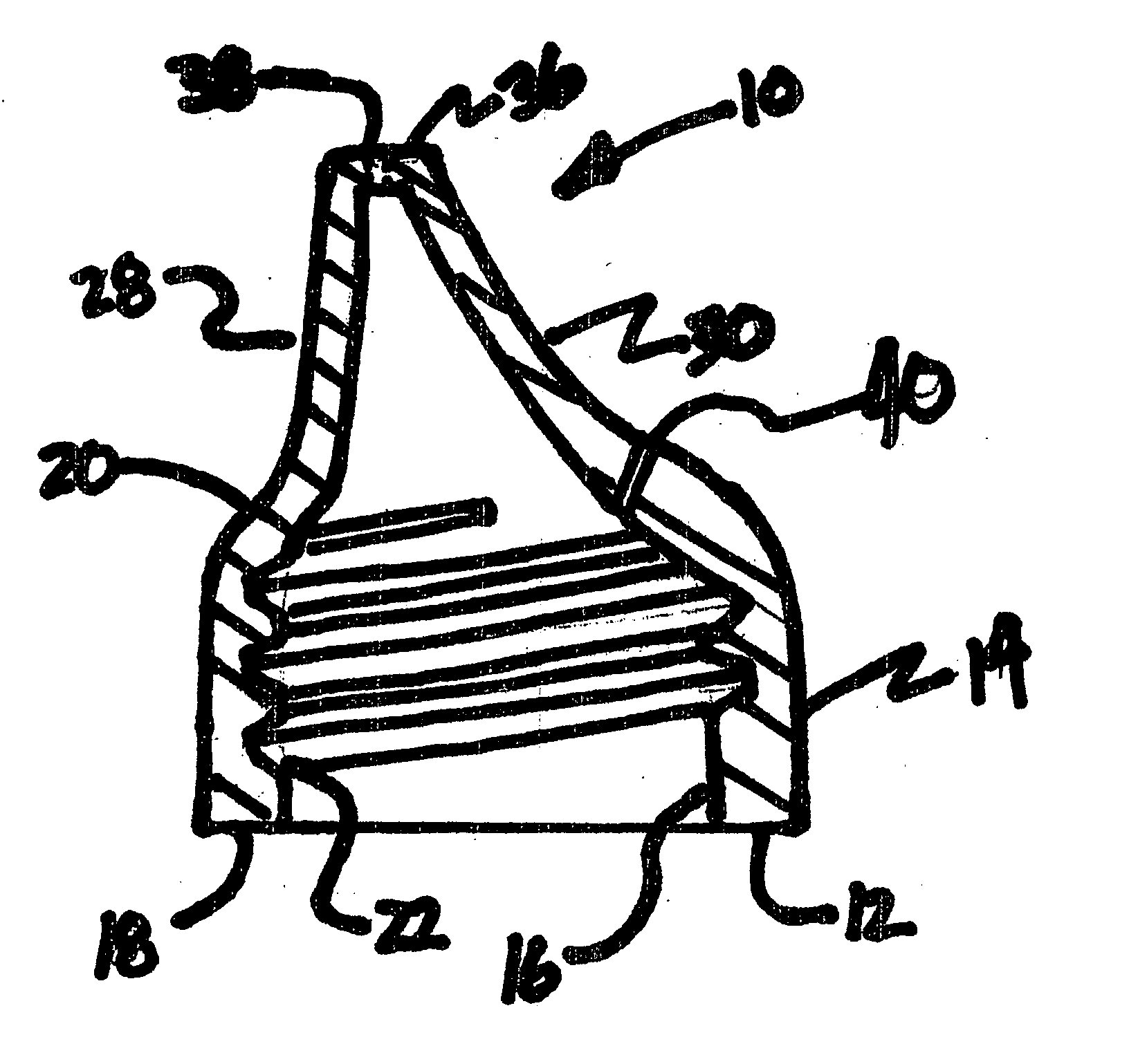
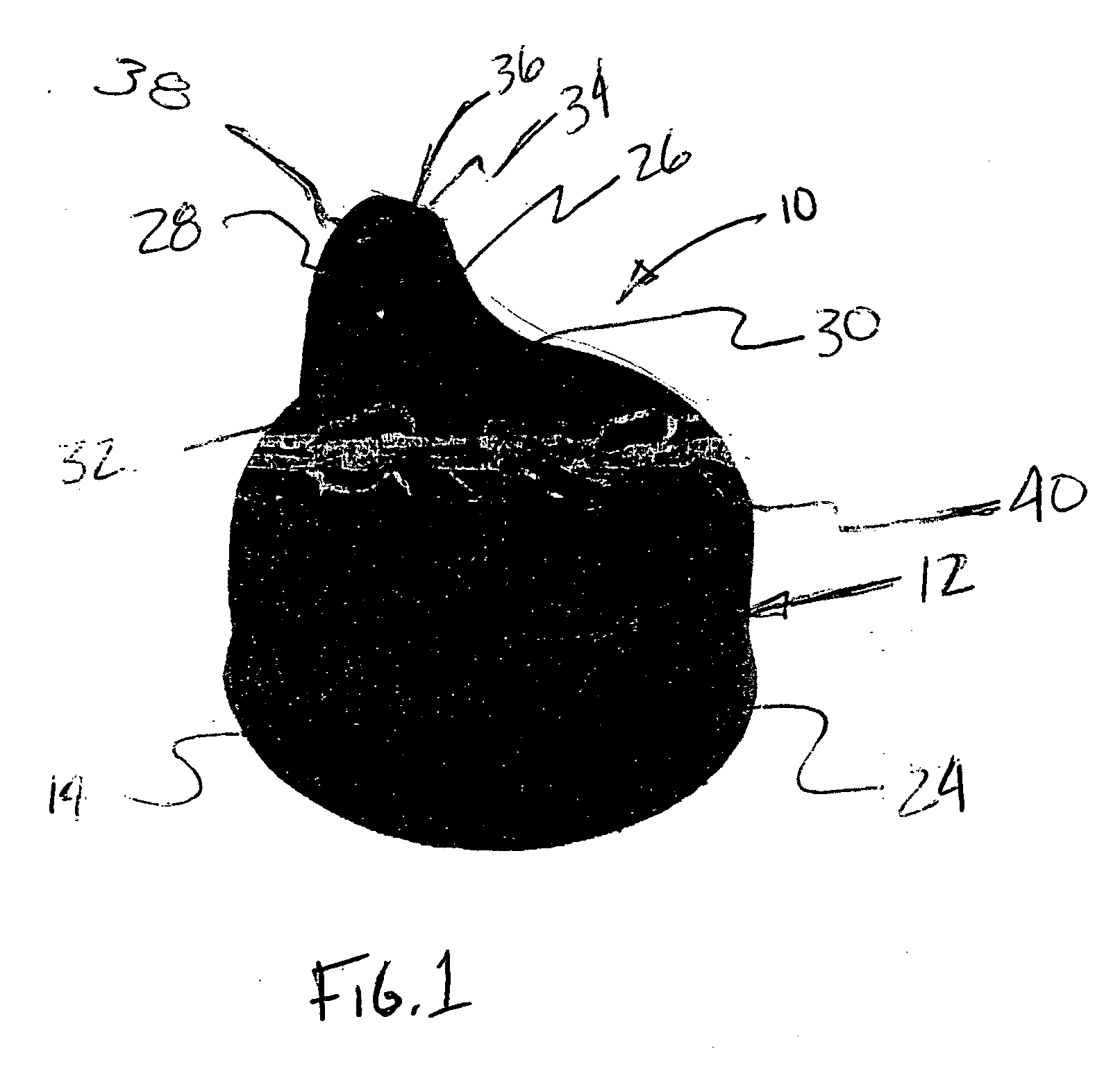
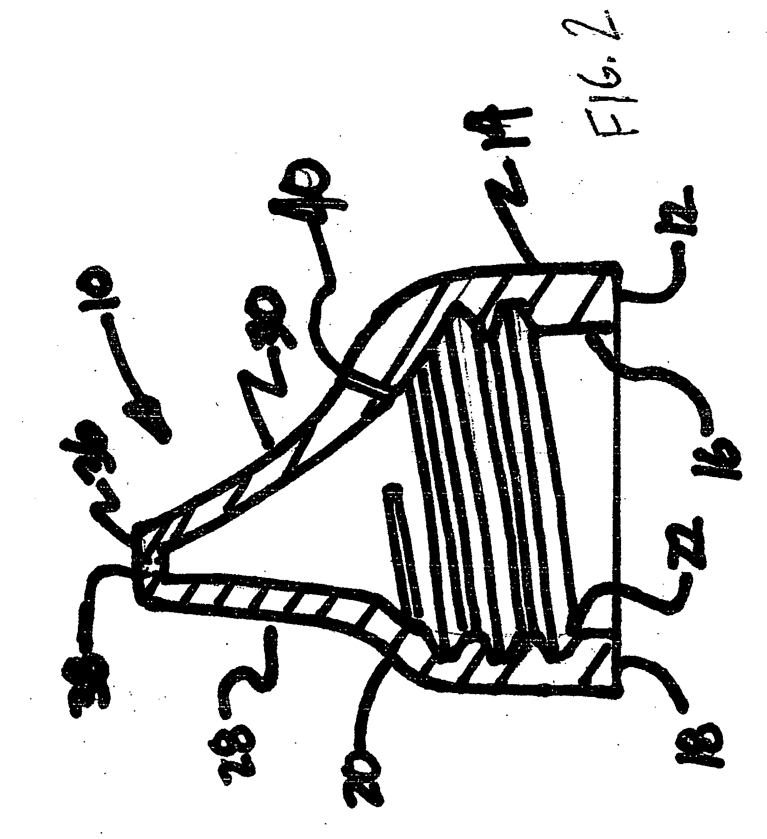
[0013] Referring to FIG. 1, a bottle top is generally shown at 10 for use on a common type beverage bottle, such as, but not limited to, blow molded plastic bottles or glass juice bottles. Referring now to FIG. 2, the bottle top 10 comprises a base cylinder 12 which is defined by an outer surface 14 and an inner surface 16 that extends from a first edge 18 to a distal top surface 20. The inner surface 16 includes threads 22 for mating engagement with any number of standard bottle threads. Referring to FIG. 1, the outer surface 14 includes a series of friction inducing protrusions 24, such as generally vertical ribs, for inducing friction to aid the addition or removal of the bottle top 10 to a bottle.

[0014] The top surface 20 includes a channel 26 that is located adjacent to the base cylinder 12 and extends upwardly from the top surface 20 for channeling the liquid flow. The channel 26 includes a generally vertical base wall 28, adjacent to the base cylinder 12, and an angled guidi...


PUM


Abstract

A bottle top for use in controlling the flow of dispensing fluids from common bottles which includes a base cylinder with an inner and outer wall and being partially enclosed at one end by a top surface. The inner wall includes threading for engaging any number of common bottle types while the outer wall includes a plurality of protrusions to aid in the griping of the bottle top for placing the bottle top on a bottle. The top surface includes a channel for directing the flow of the fluid towards a dispensing surface that caps the channel and includes at least two flow controlling dispensing apertures. The top surface further includes at least one inlet aperture for permitting air to enter into the bottle thereby allowing smooth fluid dispensing from the dispensing apertures.

Description

BACKGROUND OF THE INVENTION [0001] 1. Field of the Invention [0002] The subject of this invention relates to a liquid conveying bottle top and, more specifically, to a bottle top that may be placed on top of a common bottle of juice, soda, water, or similar commonly purchased beverage to aid in the conveyance of the chosen fluid to the end user. [0003] 2. Description of the Background Art [0004] For certain individuals, drinking directly from a store bought beverage bottle can be difficult. This is particularly true of the extremely young or old and those with disabilities who have difficulty in controlling the flow and, therefore, the regulation of the dispensing liquid captured therein. [0005] Currently, there are cups on the market, generically called “sipper cups,” that caregivers may use to dispense different beverages to the individuals. The sipper cups are commonly a two-piece design that requires one to have the proper container and proper lid to work together. This design h...

Claims


Application Information

Patent Timeline
IPC IPC(8): B67D3/00
CPCB65D47/06
Inventor OCHEN DIEHL, JUDITH
Owner OCHEN INDS
Why Eureka
Try Eureka