Ergonomic wheelchair propulsion system

Inactive Publication Date: 2007-02-01
DESIGN & MOTION
View PDF12 Cites 19 Cited by
  • Summary
  • Abstract
  • Description
  • Claims
  • Application Information

AI Technical Summary

Benefits of technology

[0020] The support system allows the operating lever to be supported in either a front and rear position, where the operating lever can be secured while the operating lever is not in use.
[0021] The angle of the support system in relation to the position of the chair is either fixed or adjustable for user preference, depending on the drive and user needs. The lever can lock into the support system, and can easily unlock with a tug on the hand grip. The rear support is also intended to aid those with minimal trunk stability, most likely due to a spinal cord injury, by maintaining the operating lever in an accessible position. The lever can be retrieved without bending at the trunk. Additionally, the supports prevent the operating lever from coming into contact with the ground or from becoming an obstruction (e.g., fitting under tables or desks).
[0022] The described methods for MWC propulsion by the new invention limit wrist and shoulder kinematics to a safe range. The wrist will not be in a position of flexion, extension, or ulnar or radial deviation at greater than 15 degrees from a neutral position during any period of propulsion. The shoulder will be maintained in a neutral position, internal rotation is limited and the potential for abduction is minimized. The MWC user can also retain his or her grasp on the hand grip at all times. The operating lever used in the present invention is not fixed to the wheel. Consequently, the user does not have to release his or her grasp of the operating lever during propulsion. Back posture is also significantly safer when using the present invention. The us

Problems solved by technology

This propulsion system addresses repetitive strain injuries, as well as hand and finger burns; blisters and calluses; difficulty in controlling the chair when the user's hands slip; injury due to small

Method used


Image

  • Ergonomic wheelchair propulsion system
  • Ergonomic wheelchair propulsion system
  • Ergonomic wheelchair propulsion system

Examples


Example

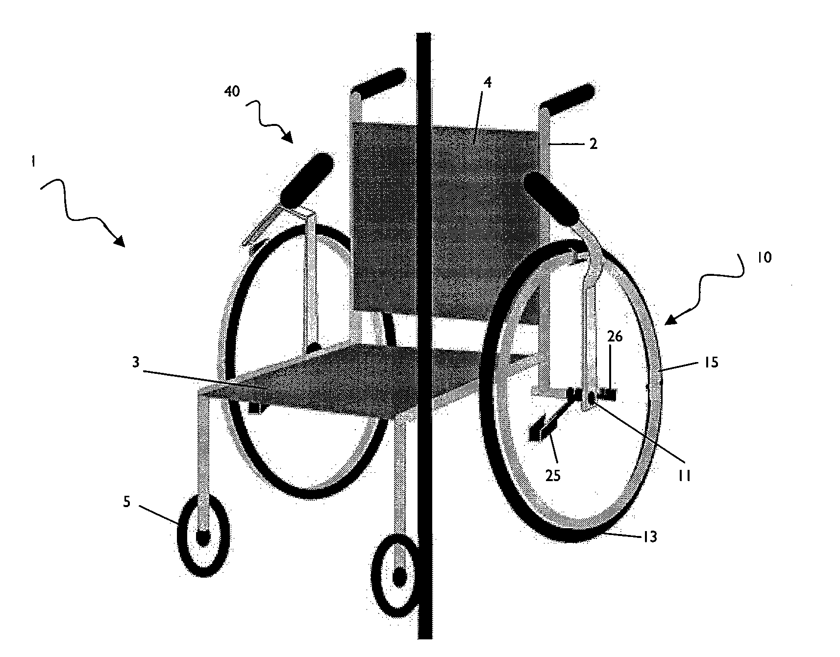
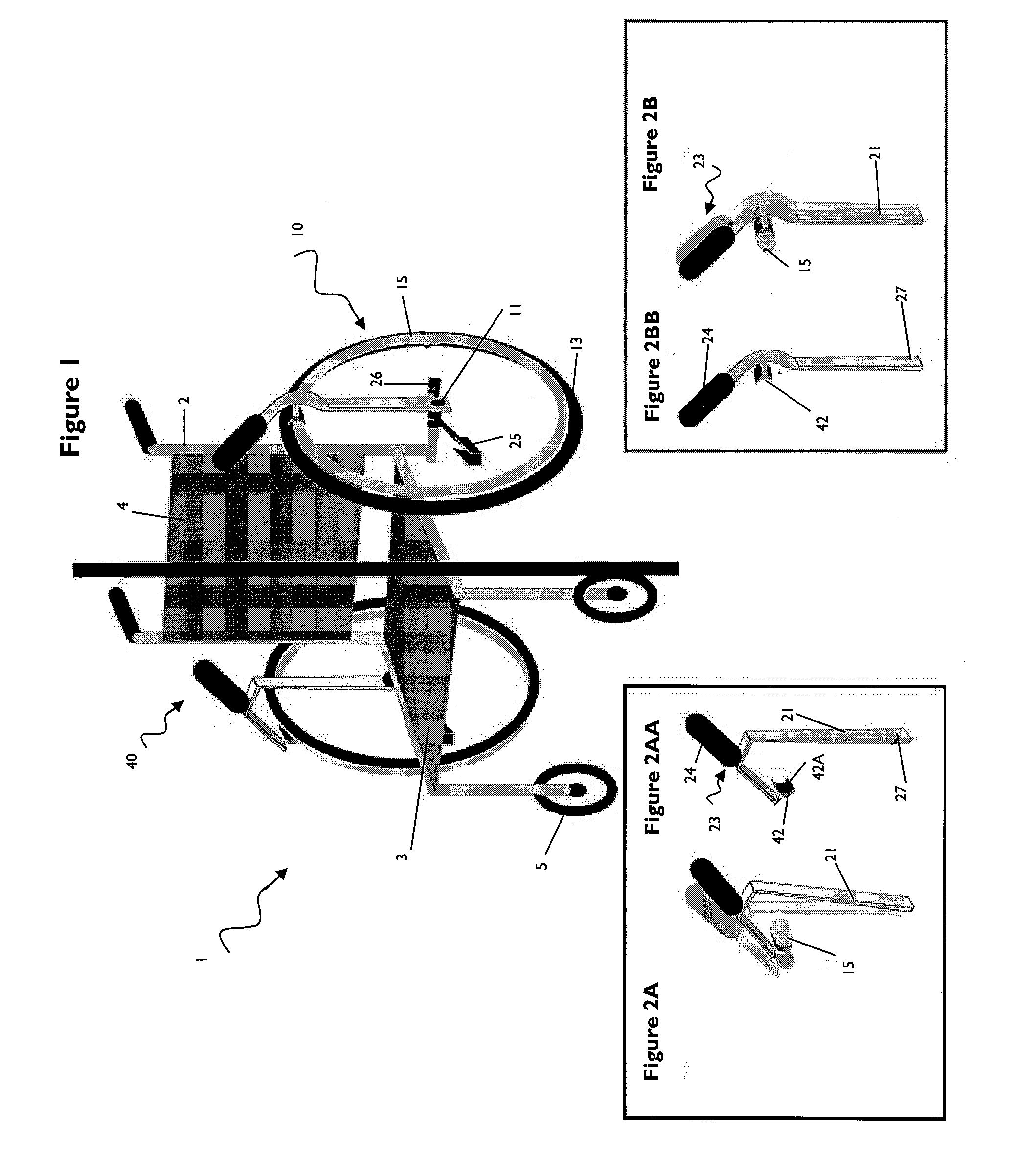
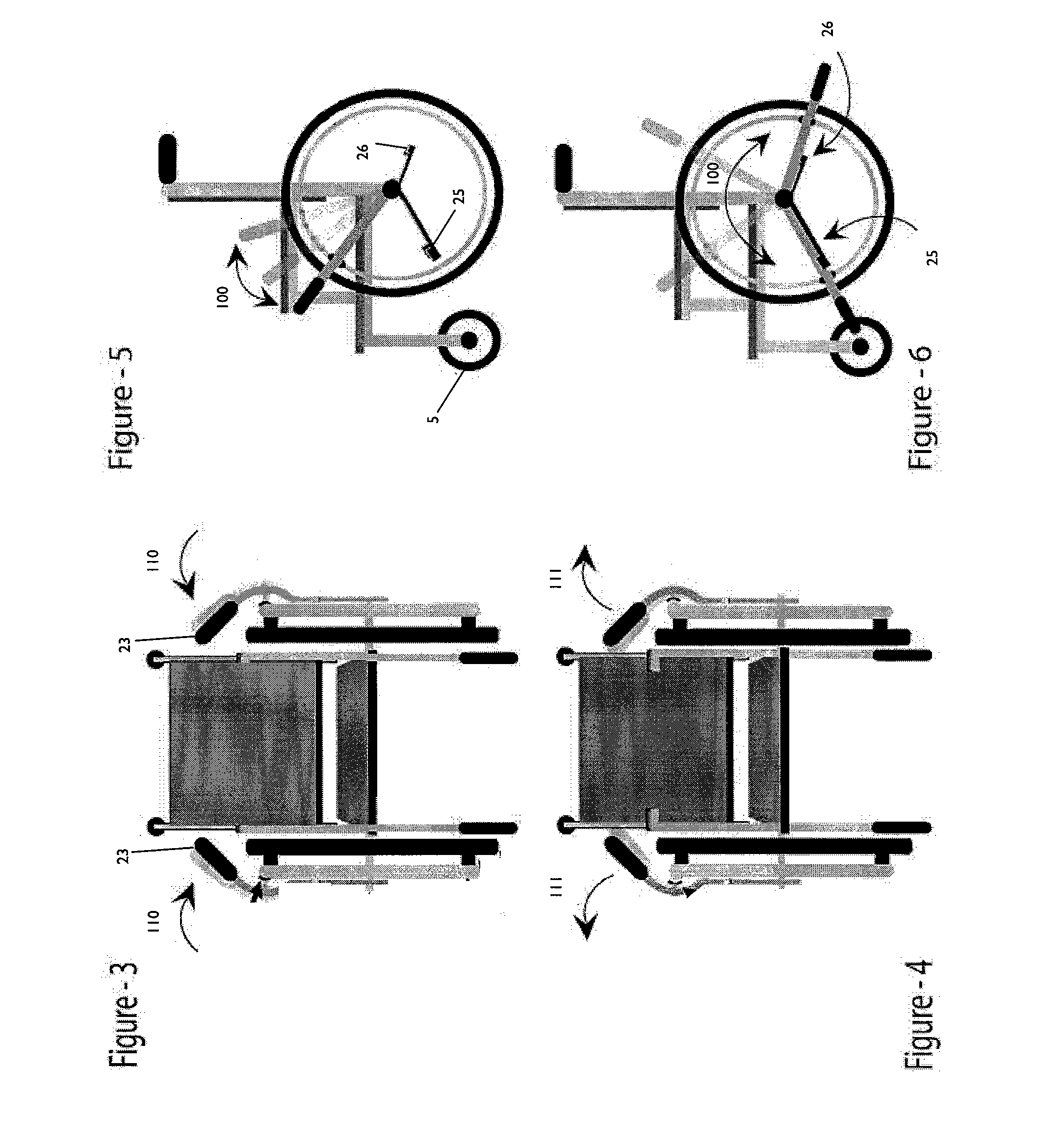
[0046] Referring now to the Figs., a manual wheelchair (MWC) 1 constructed in accordance with this invention includes a frame 2 holding a back support 4, a seat 3, two caster wheels 5 and two drive wheels 10.

[0047] Each drive wheel 10 includes an axle 11 supported by frame 2, a tire 13 and a handrim 15 that is secured to the wheel and can be grasped manually for propulsion. The tire 13 and handrim 15 are supported by the axle 11 by spokes that have been omitted for the sake of clarity. The MWC 1 can be a wheelchair modified to conform to the present invention, or can be constructed with the features of the invention integrated into the chair upon manufacturing.

[0048] As shown in the drawings, chair 1 further includes a rim drive propulsion system 40 constructed and arranged to allow a user to selectively engage or grasp indirectly the handrim 15. The rim drive propulsion system 40 includes a handle 23, covered with a hand grip 24, constructed and arranged to be gripped by a user o...


PUM


Abstract

The present application pertains to a wheelchair having a frame; a seat attached to the frame and supporting a user; two lateral drive wheels mounted on essentially horizontal axes; and a propulsion system including a handle, an operating lever supporting said handle and having a friction element mounted onto the operating lever. The operating lever is movable axially with respect to one axis between a first and second position and radially. The friction element is arranged and constructed to frictionally engage said drive wheel in the first position and radial movement of the propulsion system propels the chair in a predetermined direction.

Description

RELATED APPLICATIONS [0001] This application claims priority to U.S. Provisional Applications Ser. No. 60 / 704,214 filed on Aug. 1, 2005 and 60 / 776,851 filed on Feb. 27, 2006 and incorporated herein by reference.BACKGROUND OF THE INVENTION [0002] A. Field of Invention [0003] The present invention relates to a novel manual wheelchair (MWC) structure that enables a wheelchair user to more readily propel and brake the wheelchair in forward and rearward directions in a safe manner and with biomechanical efficiency that reduces the likelihood of injury to the user. More particularly, the application pertains to a novel manual wheel chair having an improved propulsion mechanism that can be used to move the same. [0004] B. Description of the Prior Art [0005] The present invention relates to a novel component for wheelchairs. The invention enables a wheelchair user to more readily propel and brake the wheelchair in forward and rearward directions in a safe manner and with biomechanical effic...

Claims


Application Information

Patent Timeline
IPC IPC(8): B62M1/14
CPCA61G5/022A61G5/025A61G5/023
Inventor RAND, ETHANKOFFSKY, ROBERT
Owner DESIGN & MOTION
Why Eureka
Try Eureka