

Shielded pressure-actuated circuit
a technology of pressure-actuated circuits and shields, which is applied in the direction of resistors, adjustable resistors, electrical devices, etc., can solve the problems of degrading the functionality and dependability of pressure-actuated devices, including pressure-actuated potentiometers, and the degradation of the dependability of such devices, so as to achieve the effect of increasing durability
- Summary
- Abstract
- Description
- Claims
- Application Information
AI Technical Summary
Benefits of technology
Problems solved by technology
Method used
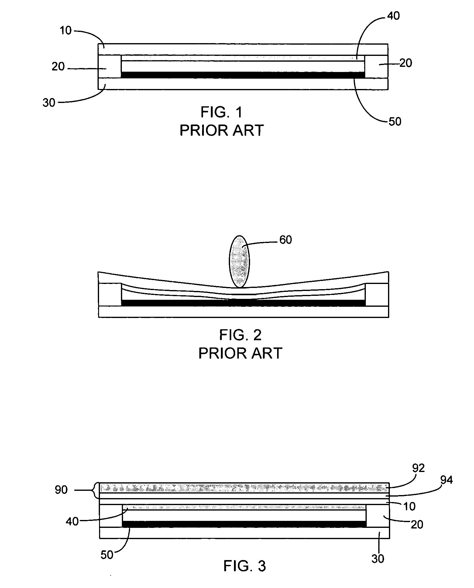
Image

Examples
Embodiment Construction
[0010] Referring now to the figures, a description of some embodiments of the present invention will be given. It is expected that the present invention may take many other forms and shapes, hence the following disclosure is intended to be illustrative and not limiting, and the scope of the invention should be determined by reference to the appended claims.
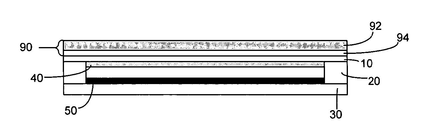
[0011] Referring now to FIG. 1, an exemplary touch-controlled apparatus in the prior art is shown with a top layer 10 having a shunt 40 adjacent to a bottom layer 30 having a conductive surface 50. Top layer 10 and shunt 40 may be affixed to one another using any method known to those skilled in the art. Similarly, bottom layer 30 and conductive surface 50 may be affixed to one another using any method known to those skilled in the art. In some embodiments, shunt 40 comprises a collector which may comprise silver or other conductive materials as is known in the art. Conductive surface 50 may comprise carbon or other materials as ...
PUM
 Abstract
Description
Claims
Application Information