Electroactive polymer-based pump

a technology of electroactive polymer and pump, which is applied in the direction of flexible wall reciprocating engine, positive displacement liquid engine, etc., can solve the problem of limiting the usefulness of some medical procedures

Active Publication Date: 2007-02-01
ETHICON ENDO SURGERY INC
View PDF5 Cites 37 Cited by
  • Summary
  • Abstract
  • Description
  • Claims
  • Application Information

AI Technical Summary

Benefits of technology

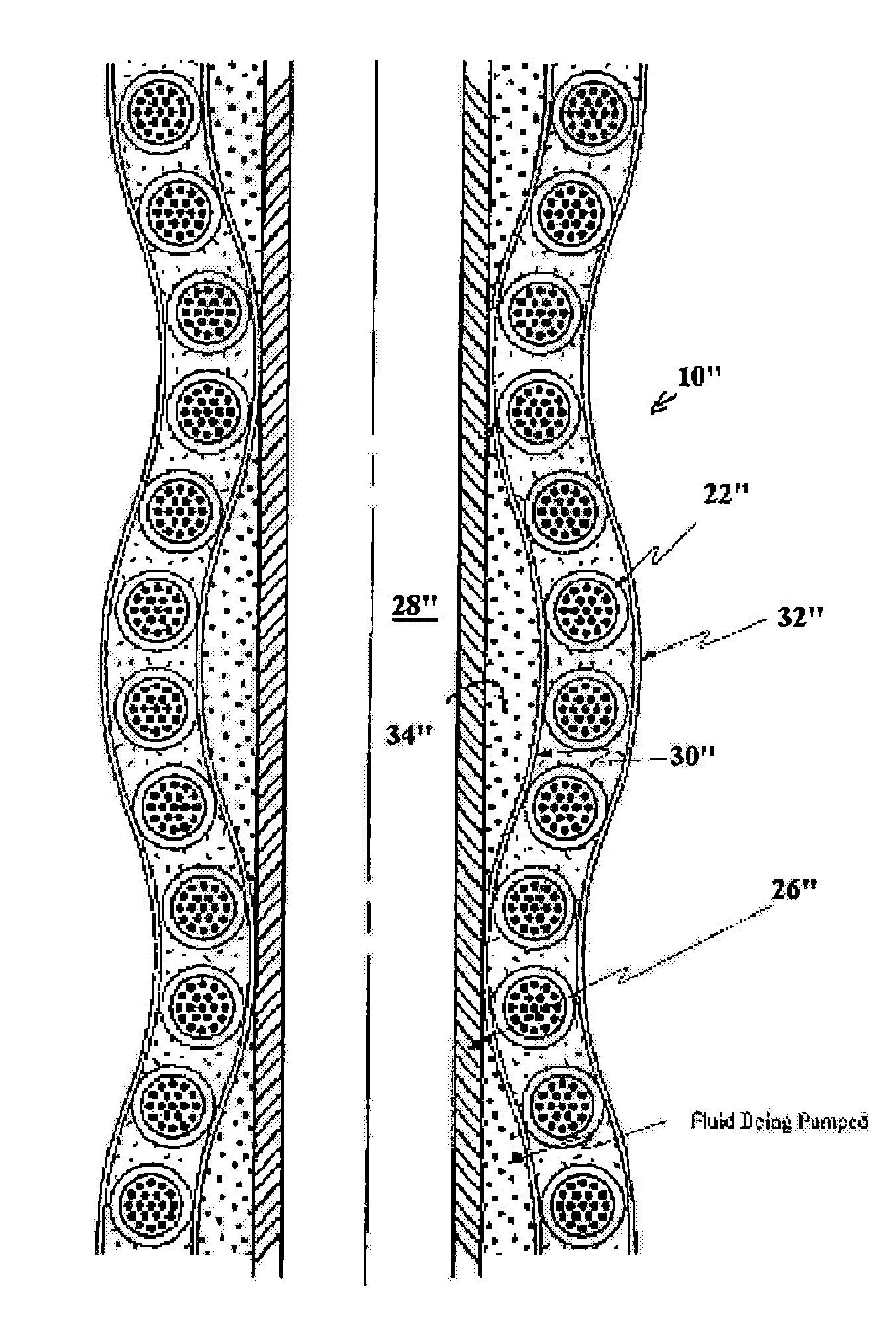
[0008] The actuators can also be arranged in a variety of configurations in order to effect a desired pumping action. In one embodiment, the actuators can be coupled to a flexible tubular member disposed within the passageway of the first member. For example, the flexible tubular member can include an inner lumen formed therethrough for receiving fluid, and the actuators can be disposed around the circumference of the flexible tubular member. The pump can also include an internal tubular member disposed within the inner lumen of the flexible tubular member such that fluid can flow between the inner tubular member and the flexible tubular member. The internal tubular member can define a passageway for receiving tools and devices. In another aspect, the actuators can be disposed within an inner lumen of the flexible tubular member and they can be adapted to be sequentially activated to radially expand upon energy delivery thereto, thereby radially expanding the flexible tubular member. As a result, the actuators can move fluid through a fluid pathway formed between the flexible tubular member and the first member.

Problems solved by technology

While effective, current pumps require large housings to encase the mechanical pumping mechanism, gears, and motors, thereby limiting their usefulness in some medical procedures.

Method used


Image

  • Electroactive polymer-based pump
  • Electroactive polymer-based pump
  • Electroactive polymer-based pump

Examples


Embodiment Construction

[0034] Certain exemplary embodiments will now be described to provide an overall understanding of the principles of the structure, function, manufacture, and use of the devices and methods disclosed herein. One or more examples of these embodiments are illustrated in the accompanying drawings. Those of ordinary skill in the art will understand that the devices and methods specifically described herein and illustrated in the accompanying drawings are non-limiting exemplary embodiments and that the scope of the present invention is defined solely by the claims. The features illustrated or described in connection with one exemplary embodiment may be combined with the features of other embodiments. Such modifications and variations are intended to be included within the scope of the present invention.

[0035] Disclosed herein are various methods and devices for pumping fluids. A person skilled in the art will appreciate that, while the methods and devices are described for use in pumping...


PUM


Abstract

Methods and devices for pumping fluid are disclosed herein. In one exemplary embodiment, a pump is provided having a first member with a passageway formed therethrough, and a plurality of electrically expandable actuators in communication with the first member and adapted to change shape upon the application of energy thereto such that sequential activation of the activators can create a pumping action to move fluid through the first member.

Description

BACKGROUND OF THE INVENTION [0001] Pumps play an important role in a variety of medical procedures. For example, pumps have been used to deliver fluids (saline, etc.) to treatment areas during laparoscopic and endoscopic procedures, to transport blood to and from dialysis and heart-lung machines, and to sample bodily fluids for analysis. Most medical pumps are centrifugal or positive displacement pumps positioned outside the surgical field and designed to withdraw or deliver fluid. [0002] Positive displacement pumps generally fall into two categories, single rotor and multiple rotors. The rotors can be vanes, buckets, rollers, slippers, pistons, gears, and / or teeth which draw or force fluids through a fluid chamber. Conventional rotors are driven by electrical or combustion motors that directly or indirectly drive the rotors. For example, peristaltic pumps generally include a flexible tube fitted inside a circular pump casing and a rotating mechanism with a number of rollers (rotors...

Claims


Application Information

Patent Timeline
Patent Type & Authority Applications(United States)
IPC IPC(8): F04B43/08
CPCF04B43/08F04B43/12F04B43/09
Inventor SWAYZE, JEFFREY S.ORTIZ, MARK S.
Owner ETHICON ENDO SURGERY INC
Why Eureka
Try Eureka