Purge valve

a technology of purging valves and valve bodies, applied in the field of valves, to achieve the effect of increasing or enhancing the stability of the valve position

Active Publication Date: 2007-02-08
BENDIX COMML VEHICLE SYST LLC
View PDF44 Cites 20 Cited by
  • Summary
  • Abstract
  • Description
  • Claims
  • Application Information

AI Technical Summary

Problems solved by technology

However, due to the nature of their construction, which usually involves an expensive rubber to metal bonding step, purge valves typically represent a significant portion (e.g., 15-25%) of the total cost of the air dryers used for heavy vehicle air brake systems.

Method used


Image

  • Purge valve
  • Purge valve
  • Purge valve

Examples


Embodiment Construction

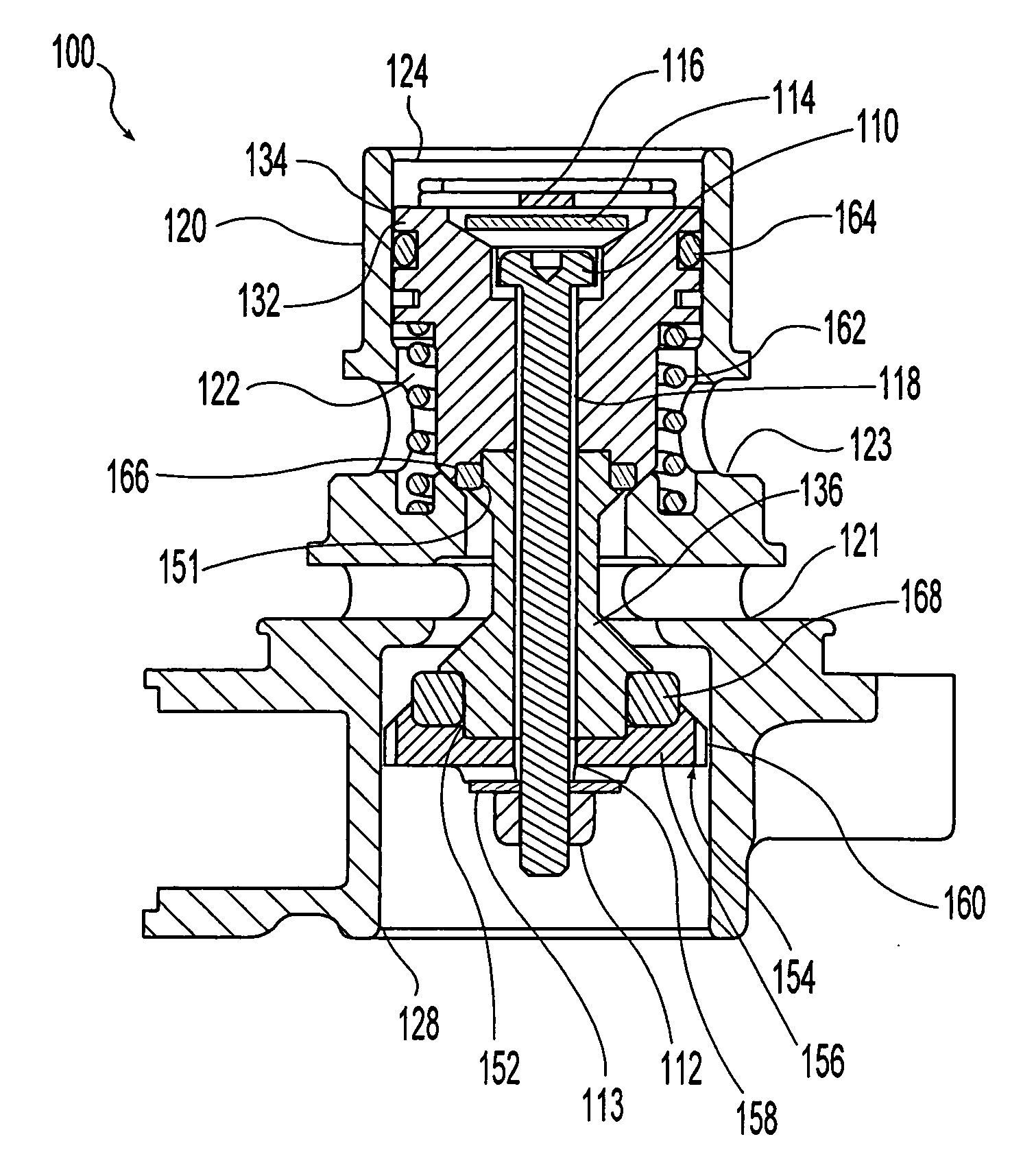
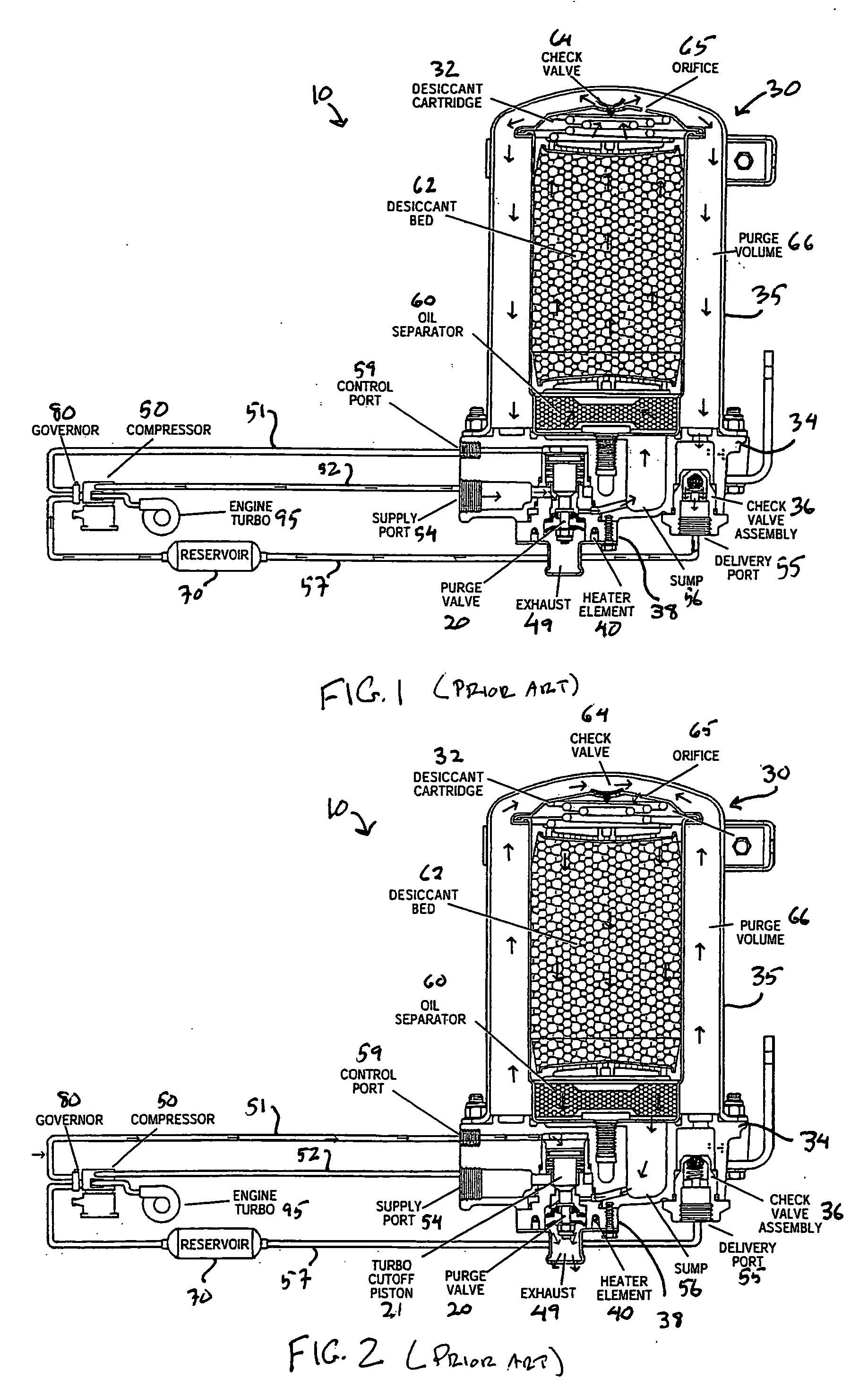
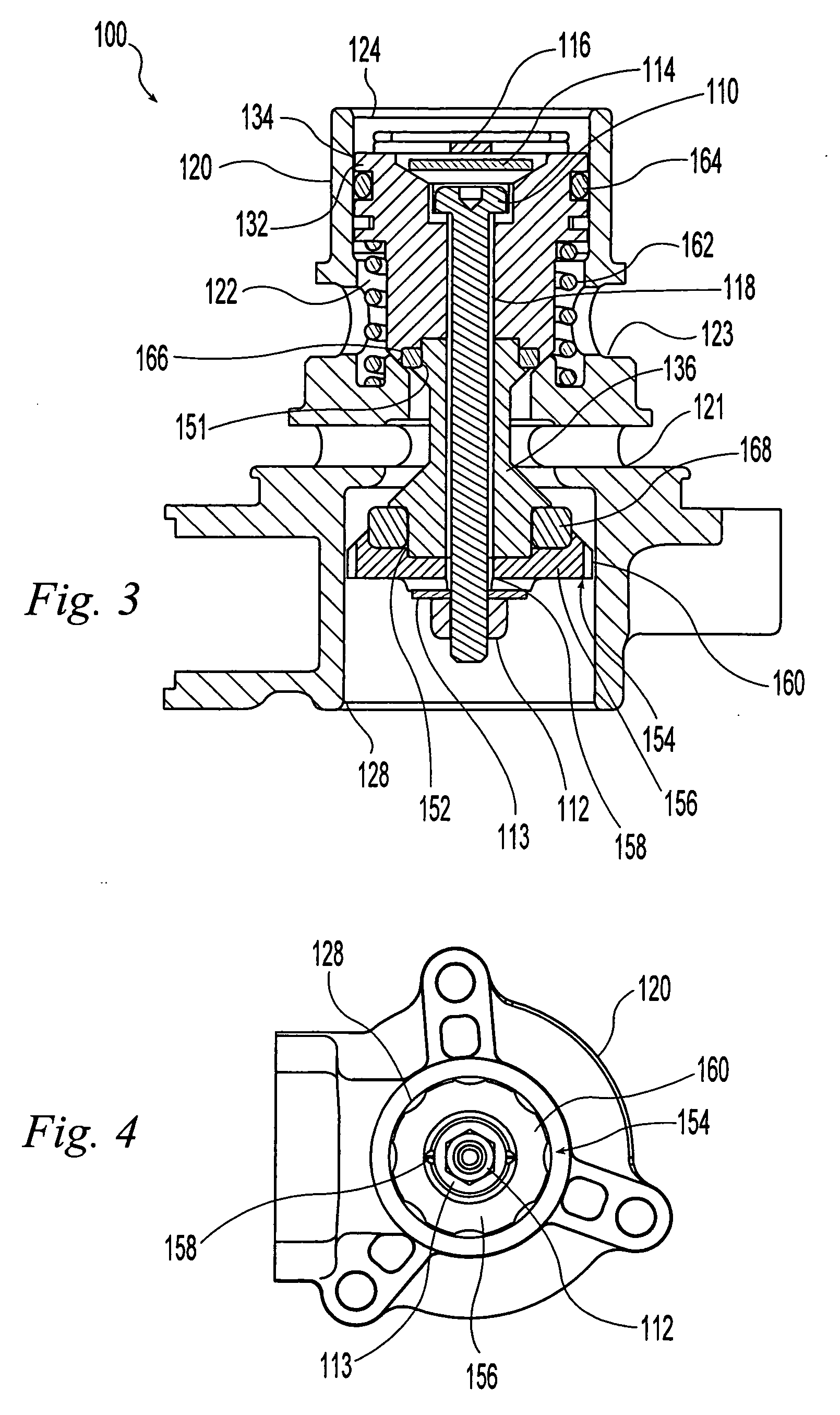
[0014] This invention relates to an air brake system that utilizes an air dryer that includes a purge valve for expelling air stream contaminants captured by the air drying system. In accordance with one embodiment of this invention, an air brake system for a heavy vehicle such as a truck or bus is provided. This system includes at least one air brake, an air compressor for providing compressed air to the air brake(s), an air dryer in communication with the air compressor for removing contaminants from the compressed air; and a purge valve for expelling contaminants from the air dryer. In accordance with another aspect of this invention, a purge valve for use with an air dryer is provided. This purge valve includes a body, a piston disposed within the body, and a valve in communication with the piston. A plurality of guide members attached to or formed integrally with the valve provide positional stability to the valve within the body and provide increased or enhanced airflow throug...


PUM

PropertyMeasurementUnit
pressureaaaaaaaaaa
positional stabilityaaaaaaaaaa
flexibleaaaaaaaaaa

Abstract

A purge valve for use with an air drying system is provided. The valve includes a housing or body, a piston disposed within the body, and a valve in communication with the piston. The respective geometries of the piston body and the valve define a circumferential cavity between and around the piston body and the valve. A sealing means is disposed within the circumferential cavity for forming a seal between the valve and the body. A plurality of guide members attached to or formed integrally with the valve provide positional stability to the valve within the body and provide enhanced airflow in, through, and around the valve.

Description

TECHNICAL FIELD OF THE INVENTION [0001] This invention relates in general to valves for use in vehicle brake systems, and in particular to a purge valve for use with air dryer systems used with commercial vehicles. BACKGROUND OF THE INVENTION [0002] Many heavy vehicles such as trucks and buses include air brake systems which utilize compressed air. Compressed air brake systems typically include a compressor that draws in atmospheric air and compresses it for use by the brake system components. Air that is drawn into the compressor usually includes water vapor and other contaminants. These contaminants should be removed from the compressed air before the compressed air enters the brake system to prevent freezing or other negative consequences. Removal of solid, liquid, and vapor air system contaminants can be accomplished by installing an air dryer system. Air dryers typically utilize a filter and a desiccant to collect and remove water and other air system contaminants before they e...

Claims


Application Information

Patent Timeline
Patent Type & Authority Applications(United States)
IPC IPC(8): B01D53/02
CPCB60T17/004B01D53/261
Inventor HOFFMAN, FRED W.QUINN, LEONARD A.NICHOLS, RANDALL W.
Owner BENDIX COMML VEHICLE SYST LLC
Why Eureka
Try Eureka