Power release mechanism

a technology of power release mechanism and power supply, which is applied in the direction of mechanical devices, fastening means, and application of locking devices, etc., can solve the problems of increasing costs, increasing costs, and not directly providing energy by the vehicle user, and stepper motors are still more expensive than a standard dc electric motor

Inactive Publication Date: 2007-02-08
MERITOR TECH
View PDF5 Cites 34 Cited by
  • Summary
  • Abstract
  • Description
  • Claims
  • Application Information

AI Technical Summary

Problems solved by technology

In such latches, a vehicle user does not directly provide the energy to release the latch via a mechanical linkage from a door handle.
It is desirable to avoid back-driving of the power release actuator to reset the mechanism after release has occurred because this requires additional control functionality which increases costs.
However, stepper motors are still more expensive than a standard DC electric motor.

Method used


Image

  • Power release mechanism
  • Power release mechanism
  • Power release mechanism

Examples


Embodiment Construction

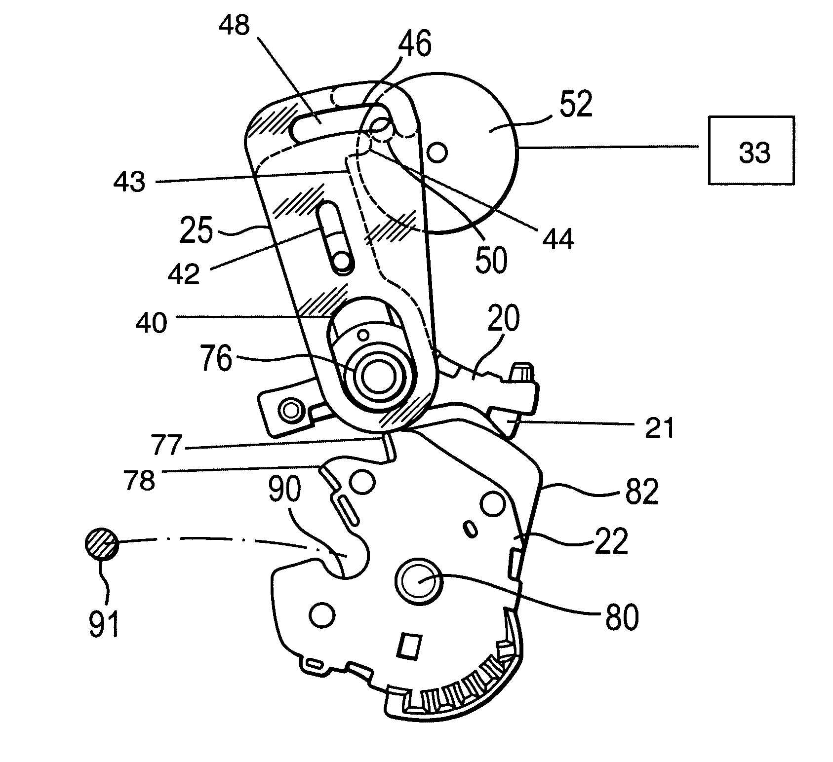
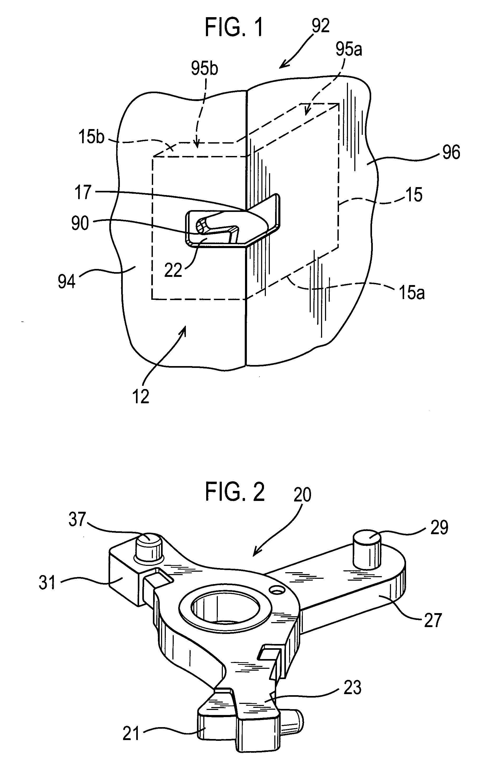
[0020]FIGS. 1 and 5 illustrate a latch 12 for a vehicle closure, in this instance a vehicle side passenger door, including a retention plate 15 having an opening 17 (shown in FIG. 1) therein to receive a striker 91 (shown in FIGS. 6A-6D). In FIG. 5, mechanical interconnections are illustrated by arrows with unbroken lines, and electrical connections are illustrated by arrows with broken lines.

[0021] As shown in FIG. 1, the retention plate 15 includes two portions: a shut face portion 15b that is arranged to be substantially parallel to a shut face 94 (the face on a trailing edge of a conventional passenger side door) of a door 92 to which the latch 12 is to be fitted and an inside face portion 15a arranged substantially 90 degrees to the shut face portion 15b and substantially parallel to an inner face 96 of the door 92 to which the latch 12 is to be fitted. The opening 17 spans the intersection of the portions 15a and 15b. The inside face portion 15a and the shut face portion 15b ...


PUM


Abstract

A power release mechanism for a vehicle door latch includes a rotary claw having a mouth to releasably retain a striker, a pawl abutment and a cam surface. The power release mechanism includes a pivotably mounted pawl resiliently biased to contact the pawl abutment to retain the claw in a latched condition and to contact the cam surface when in a released condition. A power drive formation includes an input member configured to receive drive from a power actuator and an output member. One of the input member and the output member includes first and second stall abutments, and the other of the input member and the output member includes a follower configured for contact with the first and second stall abutments during power release of the pawl. Each of the first and second stall abutments is configured to retain the follower and thereby stall the power actuator. The first stall abutment is contactable by the follower to lift the pawl from the claw. The second stall abutment is contactable by virtue of the cam surface of the claw pivoting the output member away from the input member such that the follower disengages the first stall abutment, resulting in the retention of the follower at the second stall abutment until the pawl relatches with the claw.

Description

REFERENCE TO RELATED APPLICATION [0001] This application claims priority to European Patent Application EP 05254552.2 filed on Jul. 21, 2005. BACKGROUND OF THE INVENTION [0002] The present invention relates generally to a power release mechanism. More particularly, the present invention relates to a power release mechanism for a vehicle door latch. [0003] It is known to have vehicle door latches that employ a power actuator to release the latch. In such latches, a vehicle user does not directly provide the energy to release the latch via a mechanical linkage from a door handle. Instead, an actuator, such as an electric motor, provides the energy to release the latch. Power release mechanisms are typically used on higher specification vehicles to improve the convenience for the vehicle user, or where (because of a high seal load on the door) the energy required to manually release the latch is too high for the latch to be released by a vehicle user. [0004] Nevertheless, for safety re...

Claims


Application Information

Patent Timeline
Patent Type & Authority Applications(United States)
IPC IPC(8): E05C3/06
CPCE05B81/15E05B81/14Y10T292/1082
Inventor COLEMAN, PETER J.SPURR, NIGEL V.
Owner MERITOR TECH
Why Eureka
Try Eureka