
Automatic phase converter

a phase converter and automatic technology, applied in the field of automatic phase converters, can solve the problems of often left running three-phase rotary converters, unable to provide three-phase power from utilities, and unable to meet the needs of rotary converters, so as to reduce acoustic noise and save electrical energy

Inactive Publication Date: 2007-02-15
NEWMAN JR ROBERT CHARLES
View PDF5 Cites 11 Cited by
  • Summary
  • Abstract
  • Description
  • Claims
  • Application Information

AI Technical Summary

Benefits of technology

[0007] Another object of the invention is to provide a system of an automatic phase converter, that after all three phase loads are turned off, automatically shuts itself off, thereby saving electrical energy and reducing acoustic noise.

Problems solved by technology

However, the availability of three phase power from a utility can be a problem, particularly in residential and rural areas or locations already provided with single phase power.
However, rotary converters do have a number of disadvantages which require consideration when applying these devices.
First, the rotary converter does not automatically start itself rotating.
However, due to the previously mentioned starting sequence, three phase rotary converters are often left running for long periods of time when no electrical load actually requires power.
First is an economic issue and the second is an acoustic noise issue.
A typical 25 hp rotary converter may consume about 2 kilowatts of power just idling with no connected electrical load.
This use of electrical power is a waste of energy and has no value.
Additionally, the rotary converter makes acoustic noise similar to that of an electric induction motor.
When the three phase load or loads are disconnected from the converter, the background noise of the idling converter can be quite undesirable.

Method used


Image

  • Automatic phase converter
  • Automatic phase converter
  • Automatic phase converter

Examples


Embodiment Construction

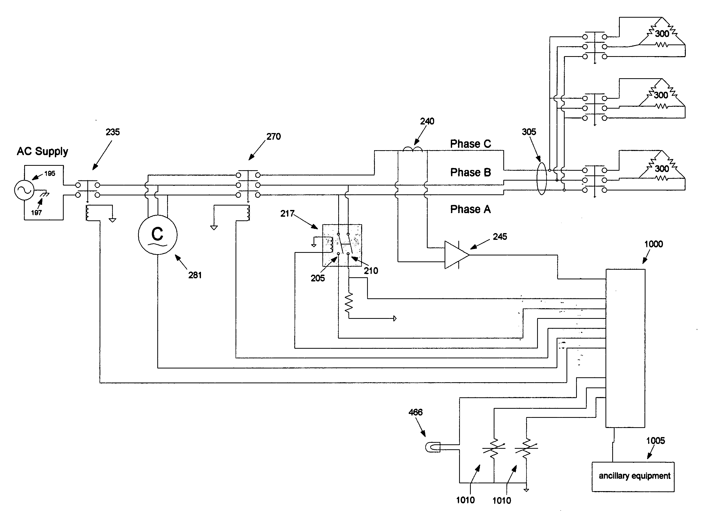
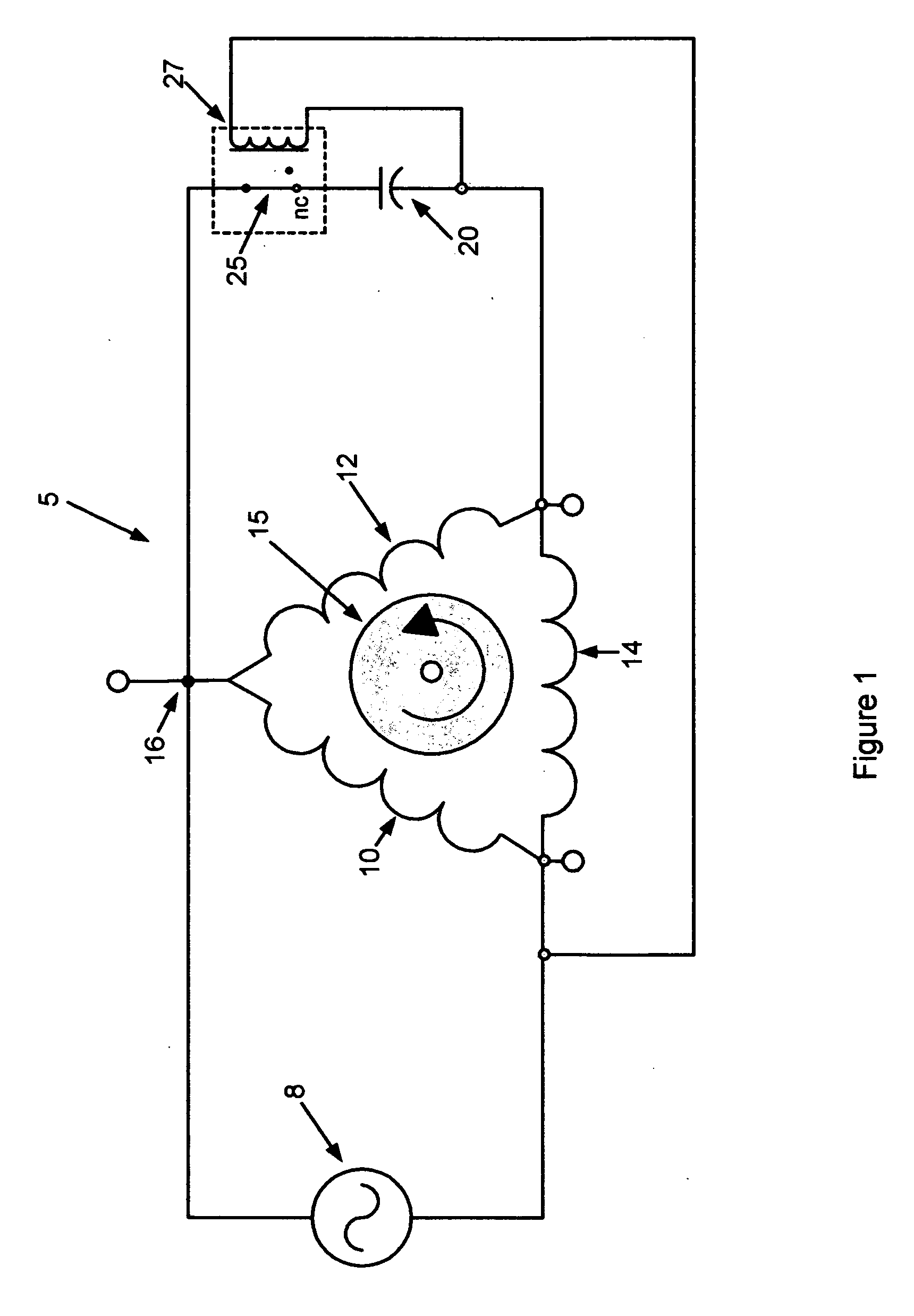
[0024] A three phase rotary converter has many similarities with a three phase induction motor. Both structures have electrical windings spaced around their periphery and a rotor structure which is free to spin. The rotor has an electrical structure which is magnetically coupled to the stationary windings located around the periphery. The stationary windings are referred to as the stator. Generally, three separate windings forming the stator are placed at about 120 degree increments around the periphery of the motor structure. In the case of a three phase induction motor, these windings are energized by AC voltages which are electrical 120 degrees out of phase with respect to each other. In the case of a three phase rotary converter, one of the windings is energized with a single phase voltage. If the rotor is spun at a speed near the synchronous speed of the structure and an appropriate AC voltage is applied to the drive winding, the rotor will continue to spin. This action is very...


PUM


Abstract

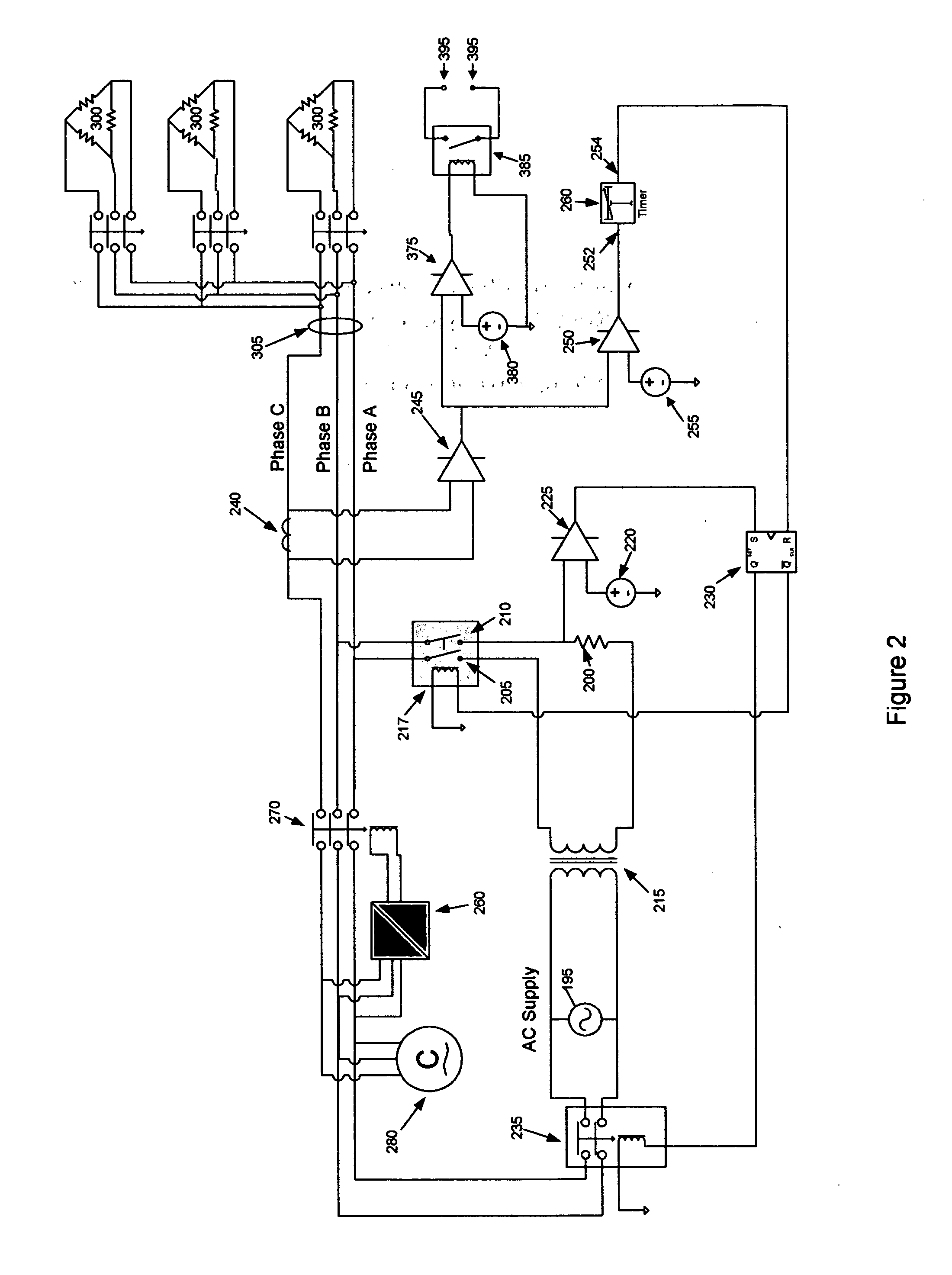
Systems for converting single phase power to three phase power are well known, however, these systems may be noisy and wasteful of electrical power because they are prone to being left on for long periods of time when three phase power is not required. To overcome these disadvantages, these converters would be manually started and stopped as necessary. This invention solves these problems by providing a system that automatically controls a three phase converter based on electrical characteristics of the connected three phase load. The invention may detect when a three phase load requires power to operate and enables a three phase converter to provide the required power. Upon completion of the requirement of power, the system of the invention may shut down the converter. Additionally, the system of the invention may signal other electrical devices based on various electrical conditions of the connected three phase load.

Description

BACKGROUND OF THE INVENTION [0001] In the field of AC power conversion a technology for transforming single phase AC voltage to three phase AC voltage has existed in the form of rotary conversion. The rotary converter is known to be a very reliable and durable mechanism for achieving the conversion of single phase voltage into three phase voltage. The benefits of operating equipment on three phase power have long been recognized and appreciated. Particular as it relates the operation of equipment having electric motors. However, the availability of three phase power from a utility can be a problem, particularly in residential and rural areas or locations already provided with single phase power. To overcome this problem various methods are available for converting single phase power into three phase power. These include static converters, electronic converters and rotary converters. In many situations, rotary converters are the device of choice, particularly in view of economics, re...

Claims


Application Information

Patent Timeline
IPC IPC(8): H02M5/00
CPCH02M1/36H02M5/32H02M5/14
Inventor NEWMAN, ROBERT CHARLES JR.
Owner NEWMAN JR ROBERT CHARLES
Learn More