Hearing device with a damping element

Inactive Publication Date: 2007-02-15
SIEMENS AUDIOLOGISCHE TECHN +1
View PDF7 Cites 12 Cited by
  • Summary
  • Abstract
  • Description
  • Claims
  • Application Information

AI Technical Summary

Benefits of technology

[0015] An object of the present invention is to avoid feedback in an hearing device of the type described above that can be worn behind the ear with an ear fitting piece wearable in the ear.
[0016] The above object is achieved in accordance with the present invention by a hearing device having a housing part that is wearable behind the ear of a user, an ear fitting piece wearable in the ear of the user, an earpiece tube connecting the housing part with the ear fitting piece, a microphone that acquires an acoustic input signal and emits an electrical input signal corresponding thereto, a signal processing and amplifier unit that processes and amplifies the electrical input signal to produce therefrom, and emit, an electrical output signal, an earpiece that transduces the electrical output signal into an acoustic output signal, and at least one damping element that damps mechanical vibrations transferred between the ear fitting piece and the housing part via the earpiece tube.
[0017] The use of a damped earpiece tube causes to the extent possible, no signal adulteration of the sound that is transferred from the hearing device into the ear. The transfer of mechanical vibrations from the ear fitting piece via the earpiece tube to the housing part is also largely suppressed. In comparison to a hearing device without these vibration-damping measures, feedbacks occur significantly less frequently. The invention is particularly advantageous when the earpiece tube between the ear fitting piece and the housing part is fashioned in one piece and relatively rigid and also serves for mounting and fixing the hearing device on the ear of a user.

Problems solved by technology

Hearing devices wearable behind the ear with an earpiece in the ear fitting piece, known as RIC (receiver in canal) devices, are prone to feedback in spite of the relatively large separation between the earpiece and the microphone.
Moreover, all internal mounting parts are designed such that they damp or filter out natural oscillations and structure-borne sound.
More substantial, hearing losses, however, can then no longer be fully compensated.

Method used


Image

  • Hearing device with a damping element
  • Hearing device with a damping element
  • Hearing device with a damping element

Examples


Embodiment Construction

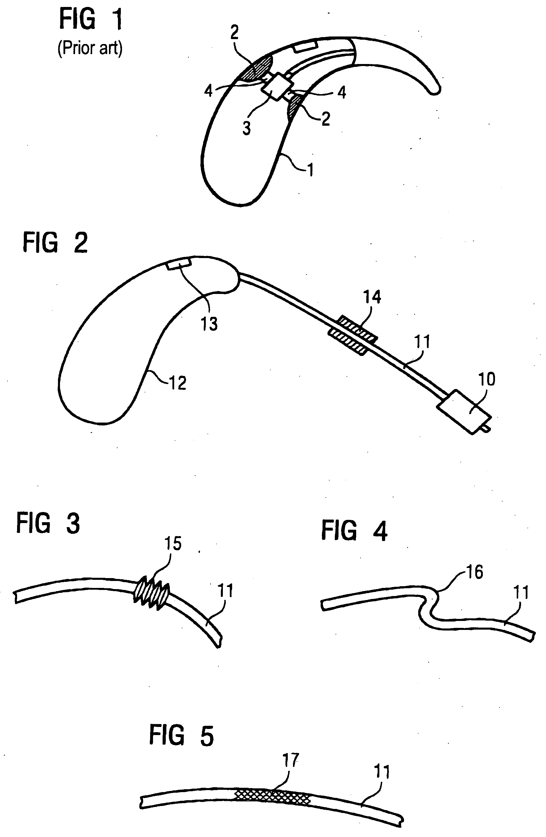
[0035] For better understanding of the invention, a known damping system is first briefly explained using FIG. 1. A housing 1 of a behind-the-ear hearing device possesses structures 2 that are internally injection-molded and serve for attachment of an earpiece. One or more damping elements 4 are accommodated between the earpiece 3 and the structure 2 or the hearing device housing 1 so that the earpiece 3 is not rigidly connected with these structures 2. This in large part prevents structure-borne sound from arriving unattenuated from the earpiece 3 to the installed microphone 5 via the hearing device housing 1. Feedbacks are thus for the most part prevented in this manner in a hearing device with an integrated earpiece 3.

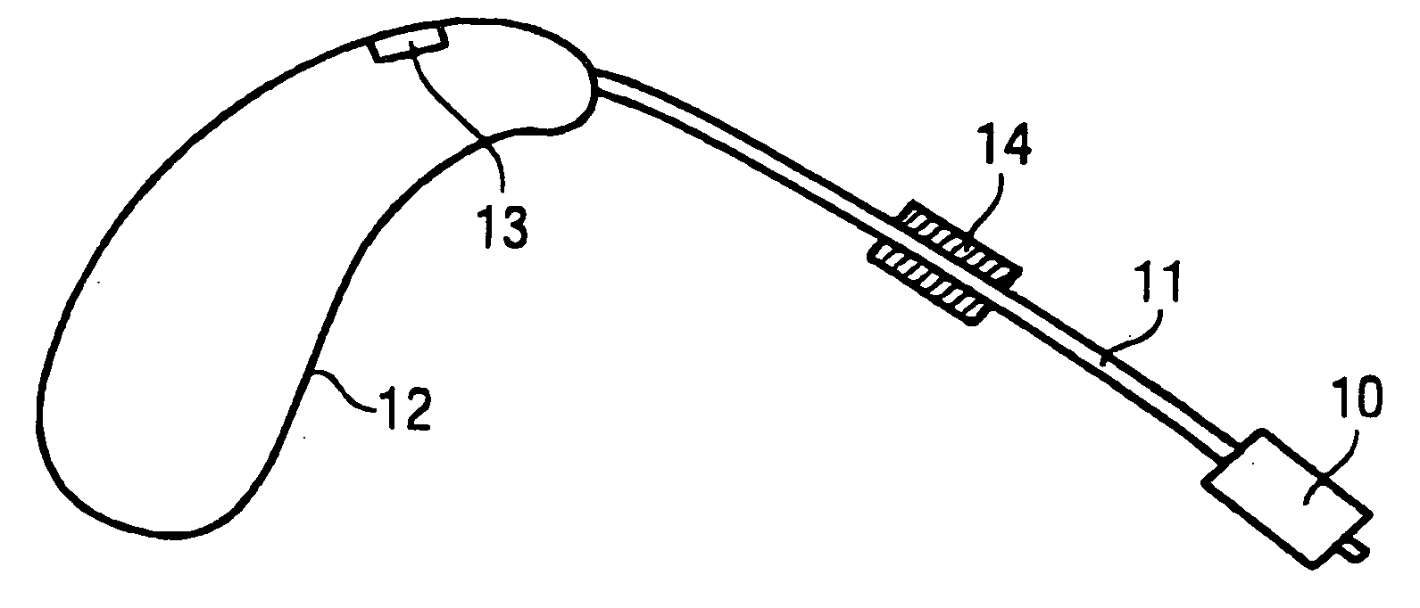
[0036] In the case of a hearing device with external earpiece 10 according to FIG. 2, vibrations of the earpiece 10 are transferred via an earpiece tube 11 to the hearing device housing 12. The microphone 13 installed in the hearing device housing 12 acquires these...


PUM


Abstract

A hearing device has an ear fitting piece, a housing part wearable behind the ear, and an earpiece tube connecting the ear fitting piece and the housing part. The transmission of mechanical vibrations between the ear fitting piece and the housing part via the earpiece tube is prevented by damping elements located in the region of the connection points between the ear fitting piece and the earpiece tube, or between the earpiece tube and the housing part. The damping elements damp mechanical vibrations in the transition region. A damping element that prevents the transmission of mechanical vibrations can also be present on or in the earpiece tube. The feedback tendency in the appertaining hearing device is thereby reduced.

Description

BACKGROUND OF THE INVENTION [0001] 1. Field of the Invention [0002] The present invention concerns a hearing device of the type having at least one housing part wearable behind the ear, an ear fitting piece wearable in the ear, an earpiece tube connecting the housing part with the ear fitting piece, a microphone for acquisition of an acoustic input signal and emission of an electrical input signal, a signal processing and amplifier unit for processing and amplification of the electrical input signal and for emission of an electrical output signal, and an earpiece arranged in the ear fitting piece for transducing of the electrical input signal into an acoustic output signal. The invention also concerns an earpiece tube for such a hearing device. [0003] 2. Description of the Prior Art [0004] In a behind-the-ear hearing device with a housing part that can be worn behind the ear and an ear fitting piece (otoplastic) wearable in the ear, the sound is transported from the hearing device i...

Claims


Application Information

Patent Timeline
IPC IPC(8): H04R25/00
CPCH04R25/456H04R2225/63H04R2225/021H04R2225/0213H04R25/607H04R2225/0216
Inventor KLEMENZ, HARALDRASS, UWEROHRLEIN, GERHARDSAUER, JOSEPHTRAUTNER, MARKUS
Owner SIEMENS AUDIOLOGISCHE TECHN
Why Eureka
Try Eureka