Eureka AIR delivers breakthrough ideas for toughest innovation challenges, trusted by R&D personnel around the world.

Hydraulic brake system and method as well as control device for its operation

Inactive Publication Date: 2013-05-23
ROBERT BOSCH GMBH
View PDF17 Cites 23 Cited by
  • Summary
  • Abstract
  • Description
  • Claims
  • Application Information

AI Technical Summary

Benefits of technology

The present invention is a hydraulic brake system for vehicles that allows for individual pressure adjustments for each wheel brake without the need for additional isolating valves. This is achieved by using valves that can be opened or closed based on the position of the input element and the pressure requirements of the brake master cylinder. The system also includes a volume adaptation unit and an actuating unit for adjusting the pressure in the wheel brakes. The use of these valves allows for precise pressure adjustments and ensures consistent driver feedback. The system can also be used to enable additional functionalities such as ABS or ESP, and can even include a hydraulic reservoir for precharging the wheel brakes. Overall, the system provides improved performance, cost savings, and space utilization.

Problems solved by technology

This may cause him to perceive a hard brake pedal, which may be irritating to a driver.
Brake systems as described in the mentioned printed publications may produce different pedal feels in the described pressure regulation, which may be perceived as annoying by the driver.

Method used


Image

  • Hydraulic brake system and method as well as control device for its operation
  • Hydraulic brake system and method as well as control device for its operation
  • Hydraulic brake system and method as well as control device for its operation

Examples


Embodiment Construction

[0025]The present invention relates to a brake system of a vehicle. The brake system includes a hydraulic brake system, in particular.

[0026]In addition to the hydraulic brake system, the brake system may include additional brake systems, especially a regenerative brake system.

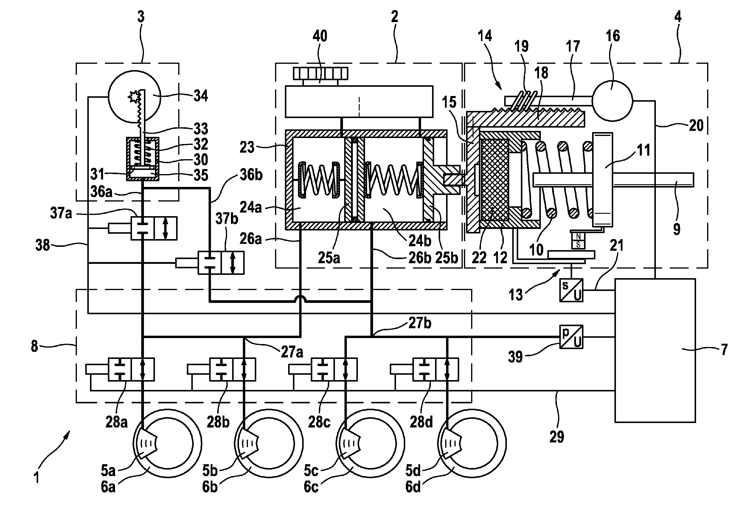
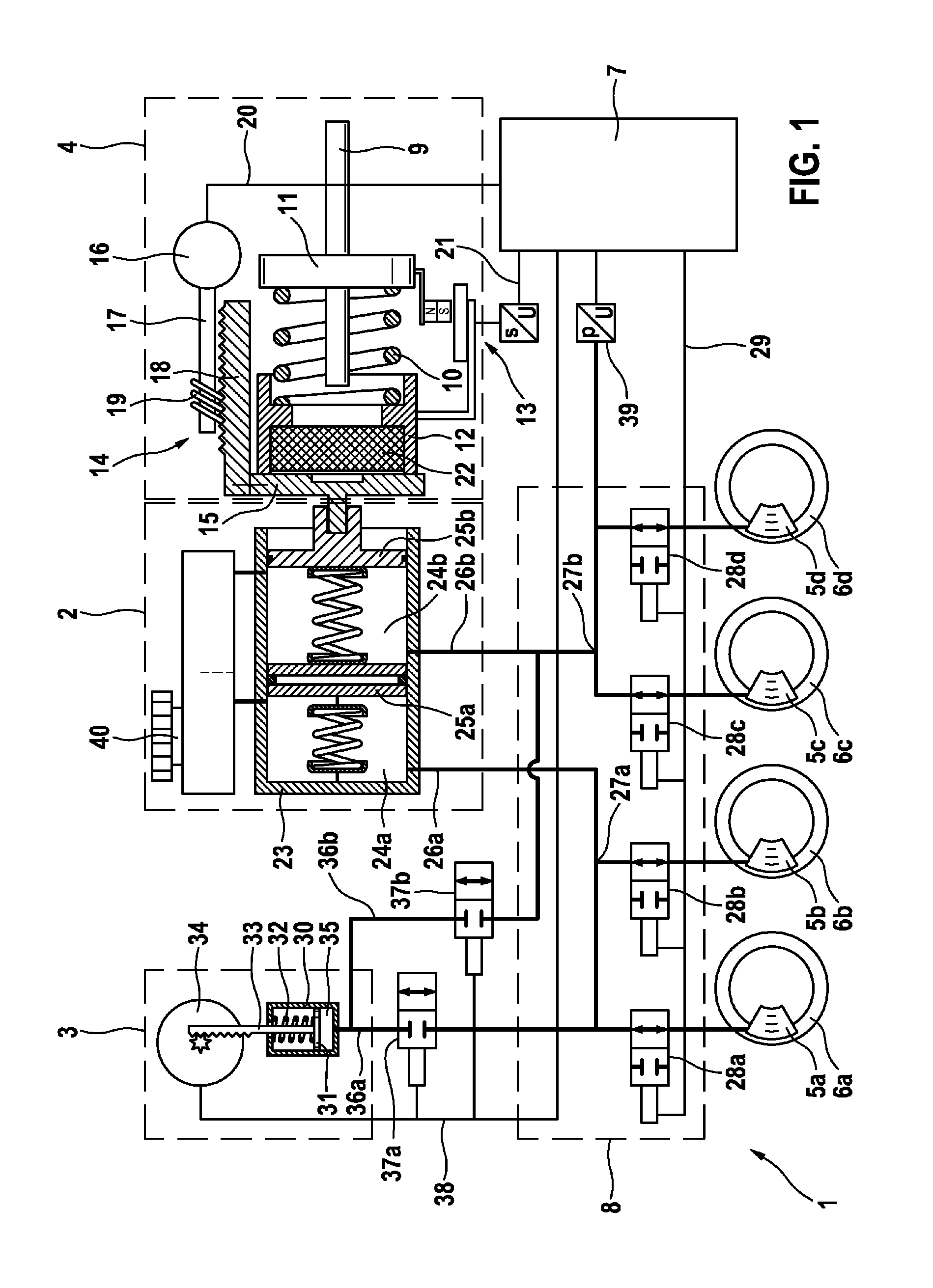
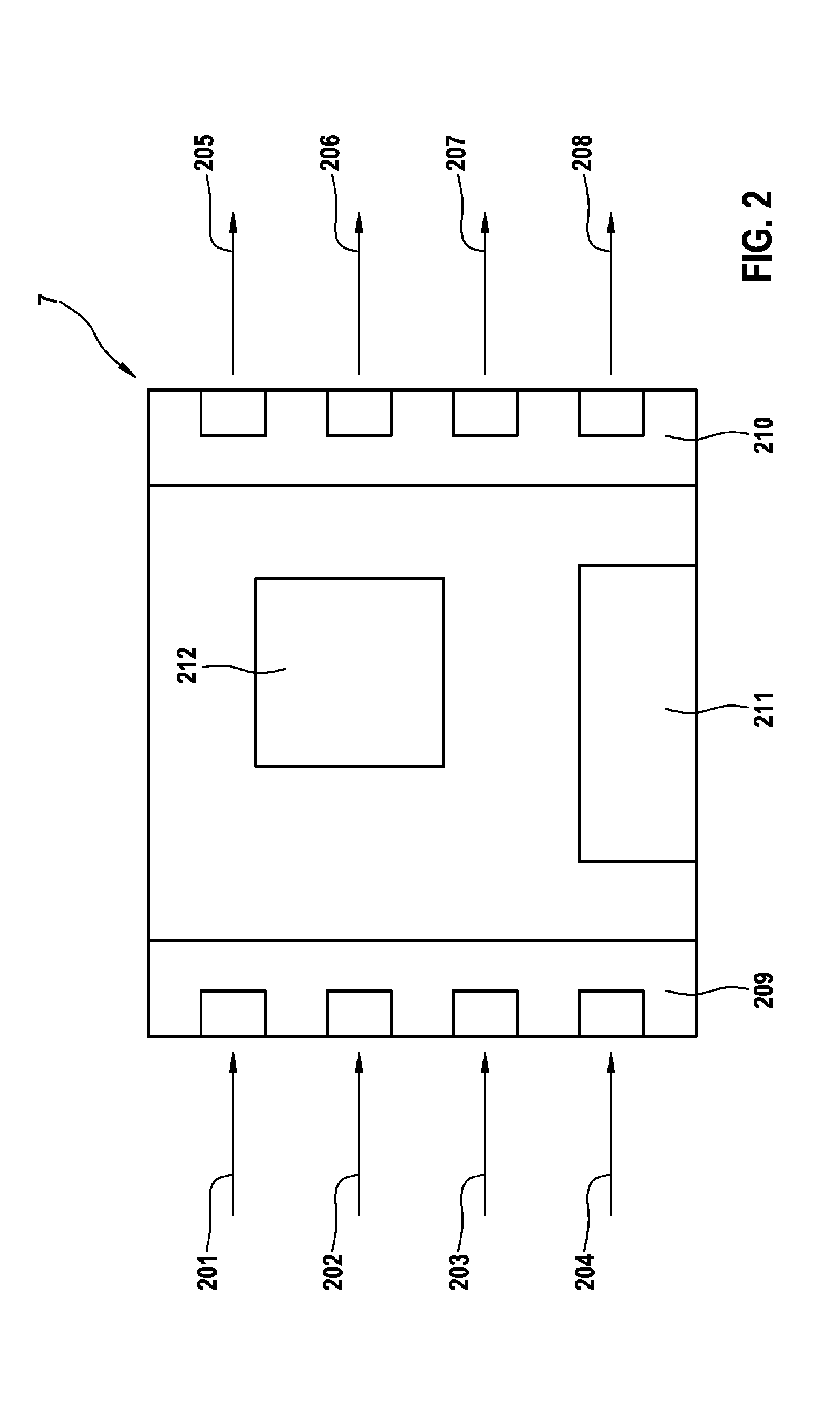
[0027]Hydraulic brake system 1 of the specific development shown in FIG. 1 essentially includes an actuating unit 4, a force-pressure conversion element 2, a hydraulic unit 8, and wheel brakes 5a-5d connected to the hydraulic unit. In addition, hydraulic brake system 1 has a control unit 7. Control unit 7 may be provided as single control unit, but it is also conceivable that control unit 7 is installed as a subunit of a control unit of the overall brake system or of the vehicle. A control within the framework of this application may also denote a regulation.

[0028]Furthermore, hydraulic brake system 1 includes a volume adaptation unit 3, which is hydraulically linked to hydraulic unit 8 and to force-pressure co...


PUM


Abstract

A hydraulic brake system has: a force-pressure conversion element, which is in hydraulic connection with at least one wheel brake cylinder of at least one wheel; a volume-adaptation element in hydraulic connection with the at least one wheel brake and the force-pressure conversion element; and as an actuating unit for actuating the force-pressure conversion element, which actuating unit has an input element. The pressure in the at least one wheel brake cylinder is adjusted by operating the volume-adaptation unit and / or the actuating unit. For this purpose an actuating state of the input element is maintained by operating the actuating unit when the volume-adaptation unit is being operated.

Description

BACKGROUND OF THE INVENTION[0001]1. Field of the Invention[0002]The present invention relates to a hydraulic brake system, in which a pressure in at least one wheel brake cylinder of the hydraulic brake system is adjusted by means of a volume adaptation device and an actuating device. A pressure adjustment may be undertaken individually for each wheel, in particular, and within the framework of an anti-lock brake control, a phase of active pressure buildup and / or a regenerative braking operation.[0003]2. Description of the Related Art[0004]Published European patent application document EP 0292648 A2 discloses a brake system having an anti-lock braking control, which essentially is made up of a hydraulic brake pressure generator actuated by a pedal, a brake-pressure modulator installed in the pressure-means paths between the brake pressure generator and the wheel brakes, with whose aid the brake pressure is variable via a volume change of a chamber containing the hydraulic medium. In...

Claims


Application Information

Patent Timeline
IPC IPC(8): B60T13/12
CPCB60T8/4018B60T13/12B60T13/745B60T8/4077B60T8/17B60T13/66B60T13/74
Inventor PFEIFFER, WOLFGANGNAGEL, WILLIHARTER, WERNERBOLZ, MARTIN-PETERBAUER, URS
Owner ROBERT BOSCH GMBH
Why Eureka
Eureka Blog
Learn More