Devices and methods for presenting and regulating auxiliary information on an image display of a telesurgical system to assist an operator in performing a surgical procedure

a technology of telesurgical system and image display, which is applied in the direction of diagnostic recording/measuring, application, catheter, etc., can solve the problems of expanding the use of minimally invasive techniques, reducing the number of surgeries currently using minimally invasive techniques, and reducing the number of surgeries

Inactive Publication Date: 2007-02-15
INTUITIVE SURGICAL
View PDF39 Cites 203 Cited by
  • Summary
  • Abstract
  • Description
  • Claims
  • Application Information

AI Technical Summary

Benefits of technology

[0013] The method typically further comprises displaying an image of the surgical site and the end effector on a display area of an image display at an operator control station of the surgical system. The image display is typically operatively connected to the image capture device so as to display, on the display area, the image of the surgical site and the end effector captured by the image capture device. The method can further include permitting an operator of the surgical system to manipulate a master control at the operator control station whilst viewing the image of the surgical site on the image display, the master control being operatively associated with the surgical instrument thereby to cause the end effector to move in response to manipulation of the master control so as to perform at least part of the surgical procedure on the patient at the surgical site.
[0014] The method yet further typically comprises operatively linking the image display to a source of selectively accessible auxiliary information related to the surgical procedure to be performed, enabling the operator selectively to access the source of auxiliary information from the operator control station so as to forward the auxiliary information to the image display, causing the auxiliary information to be displayed across the display area of the image display in response to the operator selectively accessing the source of auxiliary information at the operator control station and enabling the operator selectively to move the auxiliary information when displayed on the image display relative to the image of the surgical site displayed on the image display.

Problems solved by technology

However, only a relatively small percentage of surgeries currently use minimally invasive techniques due to limitations of minimally invasive surgical instruments and techniques currently used and the difficulty experienced in performing surgeries using such traditional instruments and techniques.
Thus, expansion in the use of minimally invasive techniques could save millions of hospital days, and consequently millions of dollars annually, in hospital residency costs alone.
There are many disadvantages relating to such traditional minimally invasive surgical (MIS) techniques.
For example, existing MIS instruments deny the surgeon the flexibility of tool placement found in open surgery.
Difficulty is experienced in approaching the surgical site with the instruments through the small incisions.
The length and construction of many endoscopic instruments reduces the surgeon's ability to feel forces exerted by tissues and organs on the end effector of the associated instrument.
Furthermore, coordination of the movement of the end effector of the instrument as viewed in the image on the television monitor with actual end effector movement is particularly difficult, since the movement as perceived in the image normally does not correspond intuitively With the actual end effector movement.
Accordingly, lack of intuitive response to surgical instrument movement input is often experienced.
Such a lack of intuitiveness, dexterity and sensitivity of endoscopic tools has been found to be an impediment to the expansion of the use of minimally invasive surgery.

Method used


Image

  • Devices and methods for presenting and regulating auxiliary information on an image display of a telesurgical system to assist an operator in performing a surgical procedure
  • Devices and methods for presenting and regulating auxiliary information on an image display of a telesurgical system to assist an operator in performing a surgical procedure
  • Devices and methods for presenting and regulating auxiliary information on an image display of a telesurgical system to assist an operator in performing a surgical procedure

Examples


Embodiment Construction

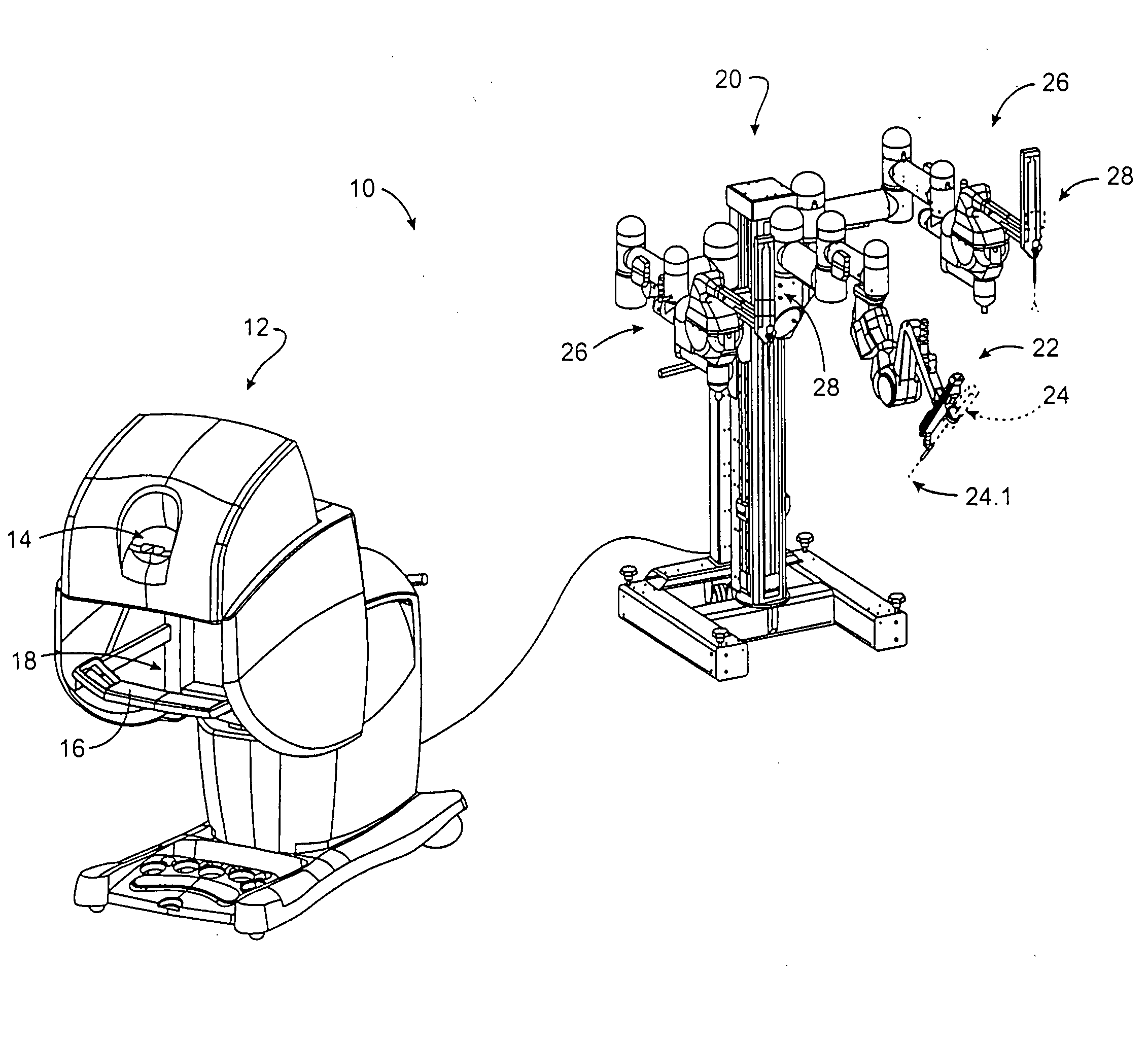
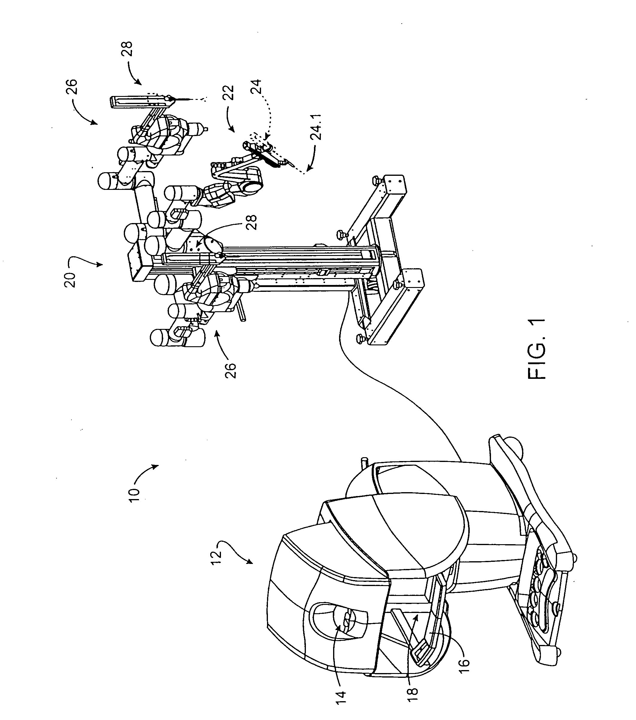
[0035] Referring to FIG. 1 of the drawings, a minimally invasive telesurgical system, or robotically controlled surgical system, in accordance with the invention is generally indicated by reference numeral 10. The system 10 includes a control station, or surgeon's console, generally indicated by reference numeral 12. The station 12 includes an image display or viewer 14 where an image of a surgical site is displayed in use. A support 16 is provided on which an operator, typically a surgeon, can rest his or her forearms while gripping two master control devices, one of which is shown in FIG. 6 of the drawings, one in each hand. The master controls are positioned in a space 18 inwardly beyond the support 16. When using the control station 12, the surgeon typically sits in a chair in front of the control station 12, positions his or her eyes in front of the viewer 14 and grips the master controls one in each hand while resting his or her forearms on the support 16.

[0036] The system 10...


PUM


Abstract

A method of performing a surgical procedure on a patient is provided. The method typically comprises positioning a surgical work station of a robotically controlled surgical system and a patient on which a surgical procedure is to be performed in close proximity relative to each other, directing a field of view of an image capture device of the surgical work station at a surgical site on the patient, at which site the surgical procedure is to be performed, and introducing at least one robotically controlled surgical instrument on the surgical work station to the surgical site so that an end effector of the surgical instrument is within the field of view of the image capture device. The method typically further comprises displaying an image of the surgical site and the end effector on a display area of an image display at an operator control station of the surgical system. The image display is typically operatively connected to the image capture device so as to display, on the display area, the image of the surgical site and the end effector captured by the image capture device. The method can further include permitting an operator of the surgical system to manipulate a master control at the operator control station whilst viewing the image of the surgical site on the image display, the master control being operatively associated with the surgical instrument thereby to cause the end effector to move in response to manipulation of the master control so as to perform at least part of the surgical procedure on the patient at the surgical site. The method yet further typically comprises operatively linking the image display to a source of selectively accessible auxiliary information related to the surgical procedure to be performed, enabling the operator selectively to access the source of auxiliary information from the operator control station so as to forward the auxiliary information to the image display, causing the auxiliary information to be displayed across the display area of the image display in response to the operator selectively accessing the source of auxiliary information at the operator control station and enabling the operator selectively to move the auxiliary information when displayed on the image display relative to the image of the surgical site displayed on the image display. The master control is typically operatively linked with the source of auxiliary information, enabling the operator selectively to access the source of auxiliary information then including permitting the operator selectively to disassociate the master control from the surgical instrument and to use the master control to access the source of auxiliary information so as to enable the auxiliary information to be displayed on the display area of the image display.

Description

RELATED APPLICATIONS [0001] This application is a continuation-in-part of co-pending U.S. patent application Ser. No. ______ , entitled “Image Shifting Apparatus and Method for a Telerobotic System,” filed Dec. 7, 1999 (Attorney Docket No. 17516-002710), the full disclosure of which is incorporated herein by reference. This application is also related to the following patents and patent applications, the full disclosures of which are incorporated herein by reference: PCT International Application No. PCT / US98 / 19508, entitled “Robotic Apparatus,” filed on Sep. 18, 1998; U.S. patent application Ser. No. 09 / 418,726, entitled “Surgical Robotic Tools, Data Architecture, and Use,” filed on Oct. 15, 1999; U.S. patent application Ser. No. 09 / 378,173, entitled “Stereo Imaging System for Use in Telerobotic Systems,” filed on Aug. 20, 1999; U.S. patent application Ser. No. 09 / 398,507, entitled “Master Having Redundant Degrees of Freedom,” filed Sep. 17, 1999; U.S. patent application Ser. No. 0...

Claims


Application Information

Patent Timeline
Patent Type & Authority Applications(United States)
IPC IPC(8): A61B5/05A61B1/00A61B19/00
CPCA61B1/00A61B1/00149A61B8/12A61B8/483A61B8/5238A61B19/22A61B19/2203A61B19/52A61B19/5212A61B2019/2223A61B2019/223A61B2019/2234A61B2019/265A61B2017/00477A61B1/0005A61B1/313A61B2090/506A61B90/36A61B34/70A61B90/361A61B34/30A61B34/37A61B34/35A61B2034/305G16H40/63G16H40/67G16H20/40
Inventor SALISBURY, J. KENNETH JR.NIEMEYER, GUNTER D.YOUNGE, ROBERT G.GUTHART, GARY S.MINTZ, DAVID S.COOPER, THOMAS G.
Owner INTUITIVE SURGICAL
Why Eureka
Try Eureka