Delay adding device and ultrasonic diagnostic apparatus

a technology which is applied in the field of adding device and ultrasonic diagnostic apparatus, can solve the problems of imposing inconvenience on a model that needs to be reduced in size and weight, and achieves the effect of less number of taps

Inactive Publication Date: 2007-02-15
GE MEDICAL SYST GLOBAL TECH CO LLC
View PDF5 Cites 1 Cited by
  • Summary
  • Abstract
  • Description
  • Claims
  • Application Information

AI Technical Summary

Benefits of technology

[0024] According to the present invention, an analog delay line has a maximum delay amount equivalent to a wavelength from over a ⅜ wavelength of a predetermined maximum wavelength of an input signal to under a 1 wavelength thereof, and tap intervals up to a delay point equivalent to ½ of a predetermined minimum wavelength of the input signal are different from tap intervals subsequent to the tap intervals. Therefore, a delay device having the analog delay line adaptable to a plurality of frequencies with a less number of taps, and an ultrasonic diagnostic apparatus equipped with such a delay device can be realized.
[0025] Delay amounts for respective receptions are quantized at minimum delay taps of an analog delay line, and if a corresponding delay tap having matched each of the quantized delay amounts exists, then a signal is sent to the tap, whereas when no matched delay tap exists, a receive signal is inverted and sent to its corresponding delay tap at which a delay of one-half wavelength is added to the delay amount. Therefore, an ultrasonic diagnostic apparatus equipped with a delay device having the analog delay line adaptable to a plurality of frequencies with a less number of taps can be realized.
[0026] In a CWD receive beamformer of an ultrasonic diagnostic apparatus, delay amounts for respective receptions are quantized at minimum delay taps of an analog delay line and a delay amount added with a delay of one-half wavelength is further determined and quantized. Delay taps identical or close to both delay amounts are selected. In the former case, a signal is inputted to each delay tap as it is, whereas in the latter case, a signal is inverted and inputted to each delay tap. Therefore, an ultrasonic diagnostic apparatus equipped with the analog delay line adaptable to a plurality of frequencies with a less number of taps.

Problems solved by technology

Such a situation imposes inconvenience on a model that needs reductions in size and weight and a reduction in cost, as in the case of, for example, a portable ultrasonic diagnostic apparatus.

Method used


Image

  • Delay adding device and ultrasonic diagnostic apparatus
  • Delay adding device and ultrasonic diagnostic apparatus
  • Delay adding device and ultrasonic diagnostic apparatus

Examples


Embodiment Construction

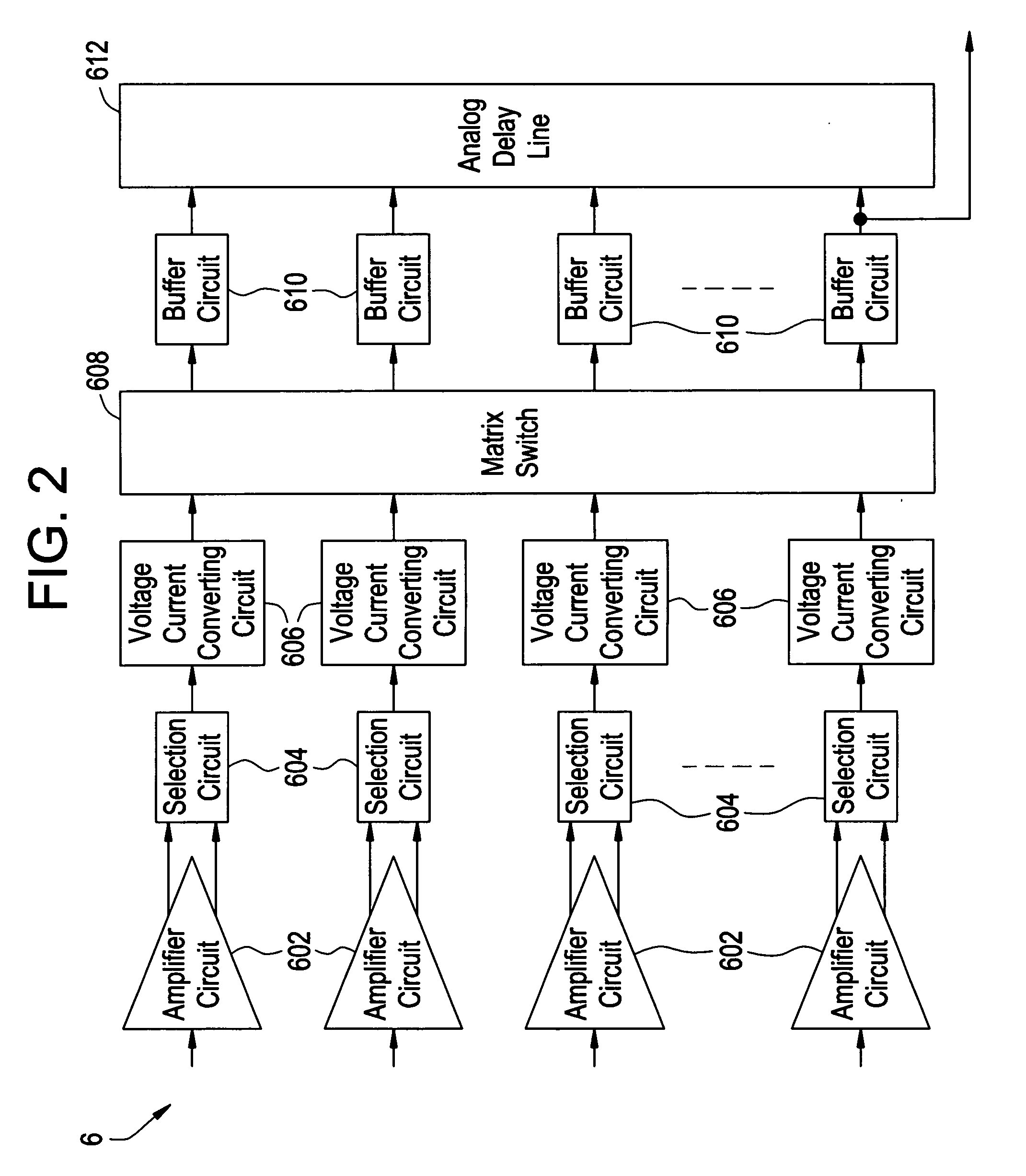
[0017] The invention according to one aspect for solving the above problems provides a delay adding device comprising an analog delay line having a plurality of taps, which delays and adds a plurality of continuous signals, wherein the analog delay line has a maximum delay amount equivalent to a wavelength from over a ⅜ wavelength of a predetermined maximum wavelength of an input signal to under a 1 wavelength thereof, and tap intervals up to a delay point equivalent to ½ of a predetermined minimum wavelength of the input signal are different from tap intervals subsequent to the tap intervals.

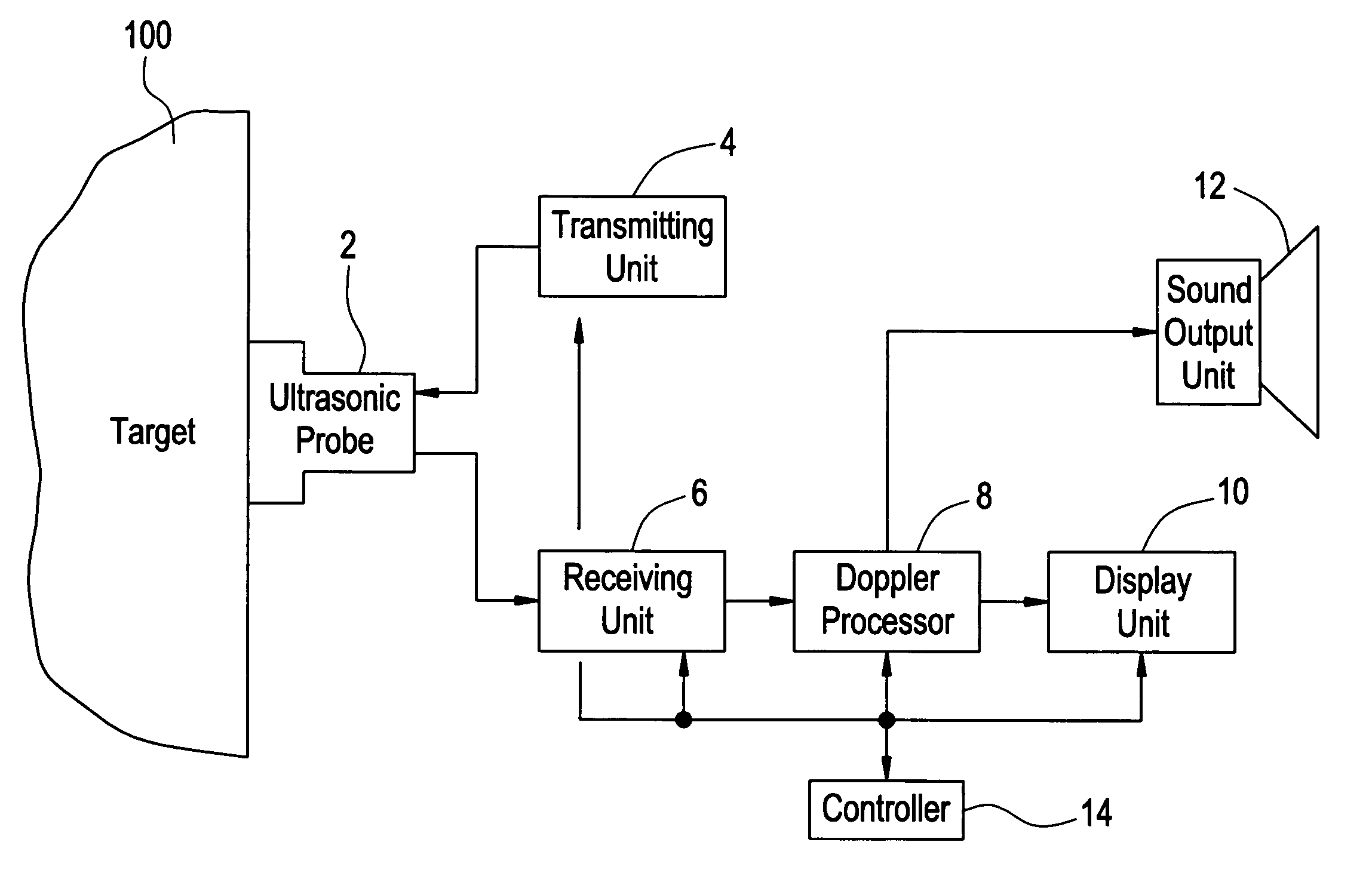
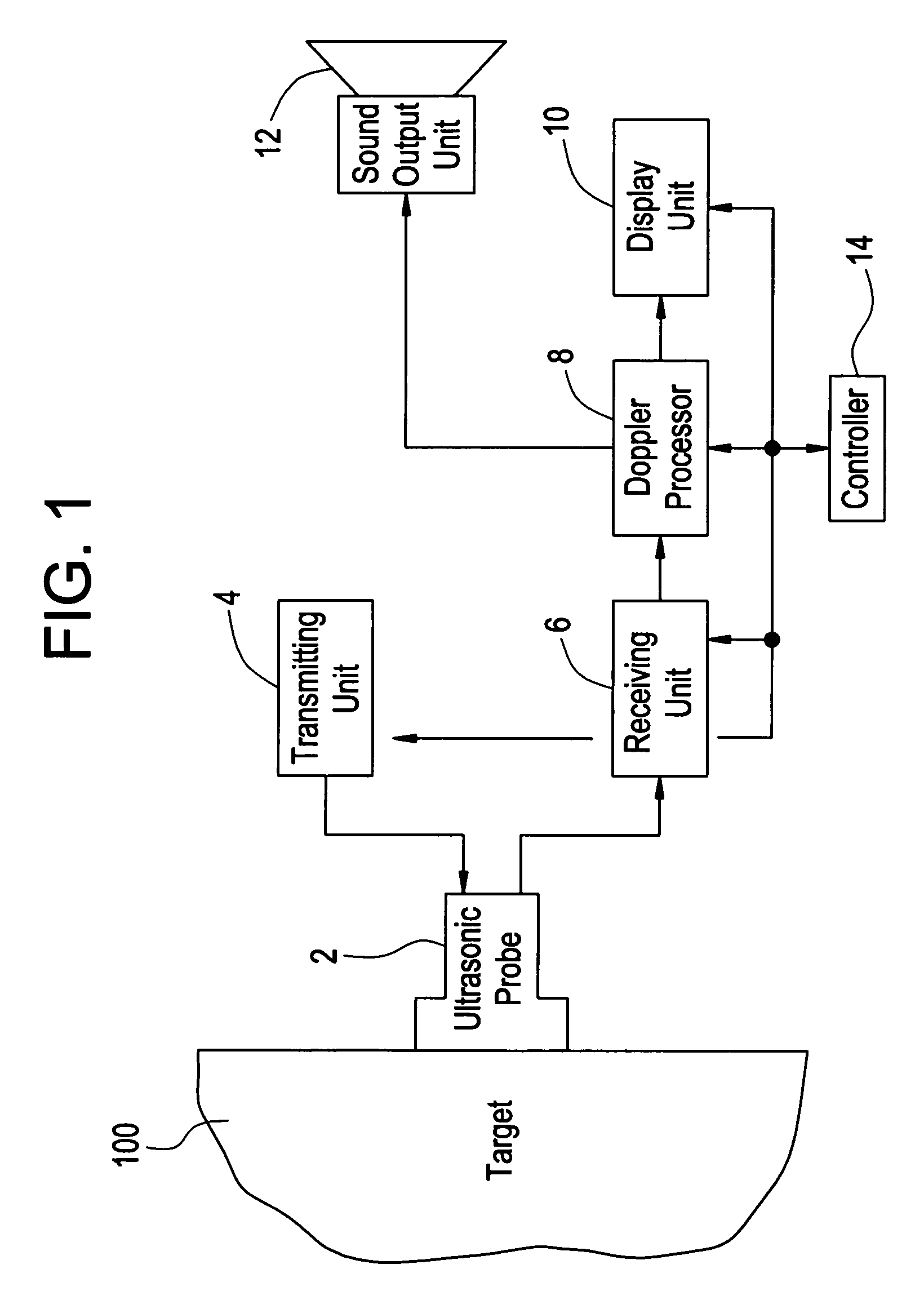
[0018] The invention according to another aspect for solving the above problems provides an ultrasonic diagnostic apparatus comprising an analog delay line having a plurality of taps, which sends a continuous ultrasonic sound, receives an echo thereof through a plurality of channels, delays and adds their receive signals by the analog delay line to thereby determine a Doppler shift, wherein th...


PUM


Abstract

The present invention aims to provide a delay device having an analog delay line adaptable to a plurality of frequencies with a less number of taps. The analog delay line has a maximum delay amount equivalent to a wavelength from over a ⅜ wavelength of a predetermined maximum wavelength of an input signal to under a 1 wavelength thereof. Tap intervals up to a delay point equivalent to ½ of a predetermined minimum wavelength of the input signal are different from tap intervals placed ahead of those. The maximum wavelength is a wavelength of a signal having a frequency of 2 MHz, for example, and the minimum wavelength is a wavelength of a signal having a frequency of 5 MHz, for example.

Description

CROSS REFERENCE TO RELATED APPLICATIONS [0001] This application claims the benefit of China Application No. 200510078665.5 filed Jun. 23, 2005. BACKGROUND OF THE INVENTION [0002] The present invention relates to a delay adding device and an ultrasonic diagnostic apparatus, and particularly to a device which delays and adds a plurality of continuous wave signals by an analog delay line having a plurality of taps, and an ultrasonic diagnostic apparatus equipped with such a device. [0003] In an apparatus which performs an ultrasonic diagnosis by a CWD (Continuous Wave Doppler), a continuous ultrasonic sound is transmitted and its echo is received by a plurality of channels. Those received signals are delayed and added by an analog delay line having plural taps to determine a Doppler shift. The delay / addition is performed to adjust or control the orientation of echo reception. [0004] By the use of the fact that the polarity of an input signal is inverted to obtain a delay effect equival...

Claims


Application Information

Patent Timeline
Patent Type & Authority Applications(United States)
IPC IPC(8): A61B8/00
CPCH03H7/32G01S15/8979A61B8/44
Inventor YU, YIGANGAMEMIYA, SHINICHI
Owner GE MEDICAL SYST GLOBAL TECH CO LLC
Why Eureka
Try Eureka