

Ultrasound diagnostic flow imaging with coded excitation
- Summary
- Abstract
- Description
- Claims
- Application Information
AI Technical Summary
Benefits of technology
Problems solved by technology
Method used
Image

Examples
Example
DETAILED DESCRIPTION OF THE DRAWINGS AND PRESENTLY PREFERRED EMBODIMENTS
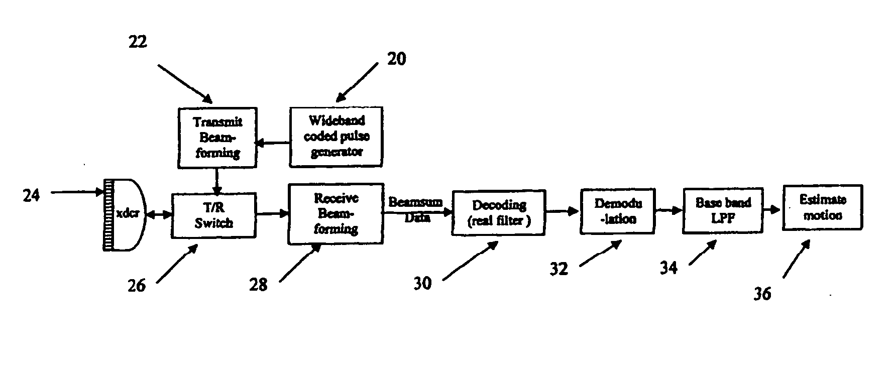
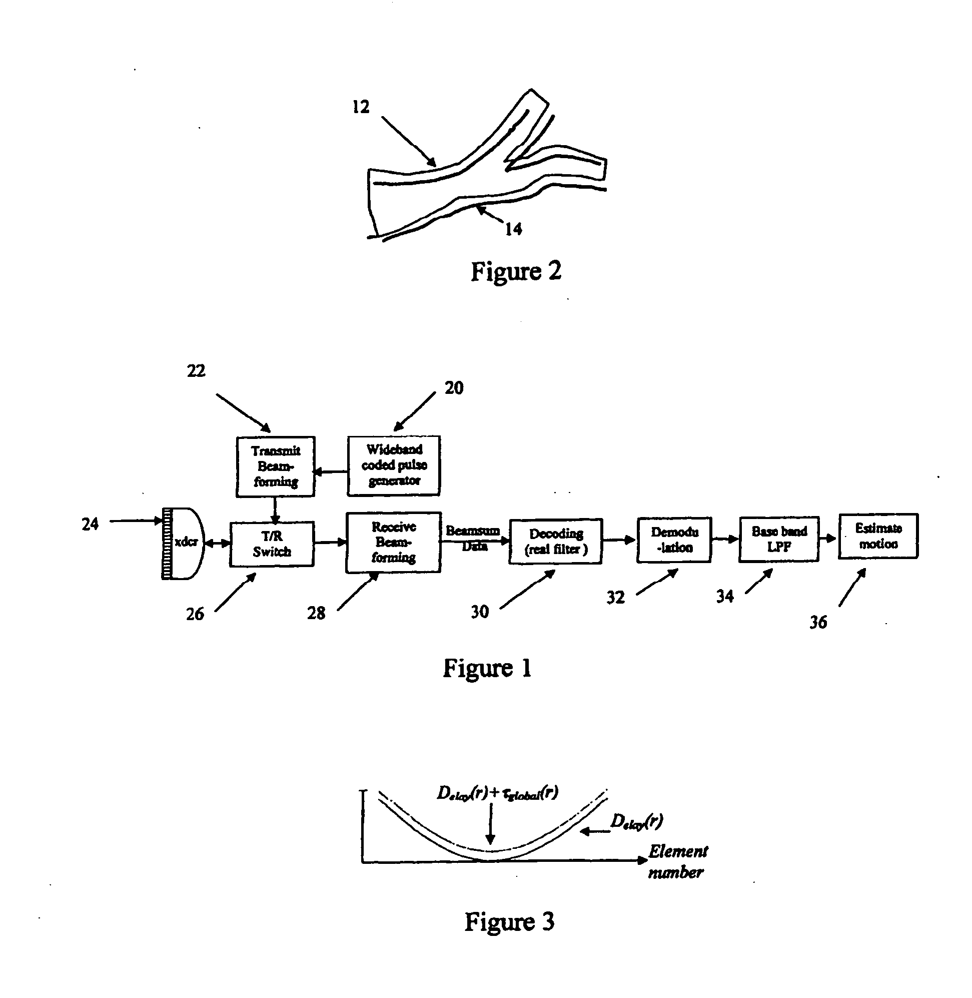
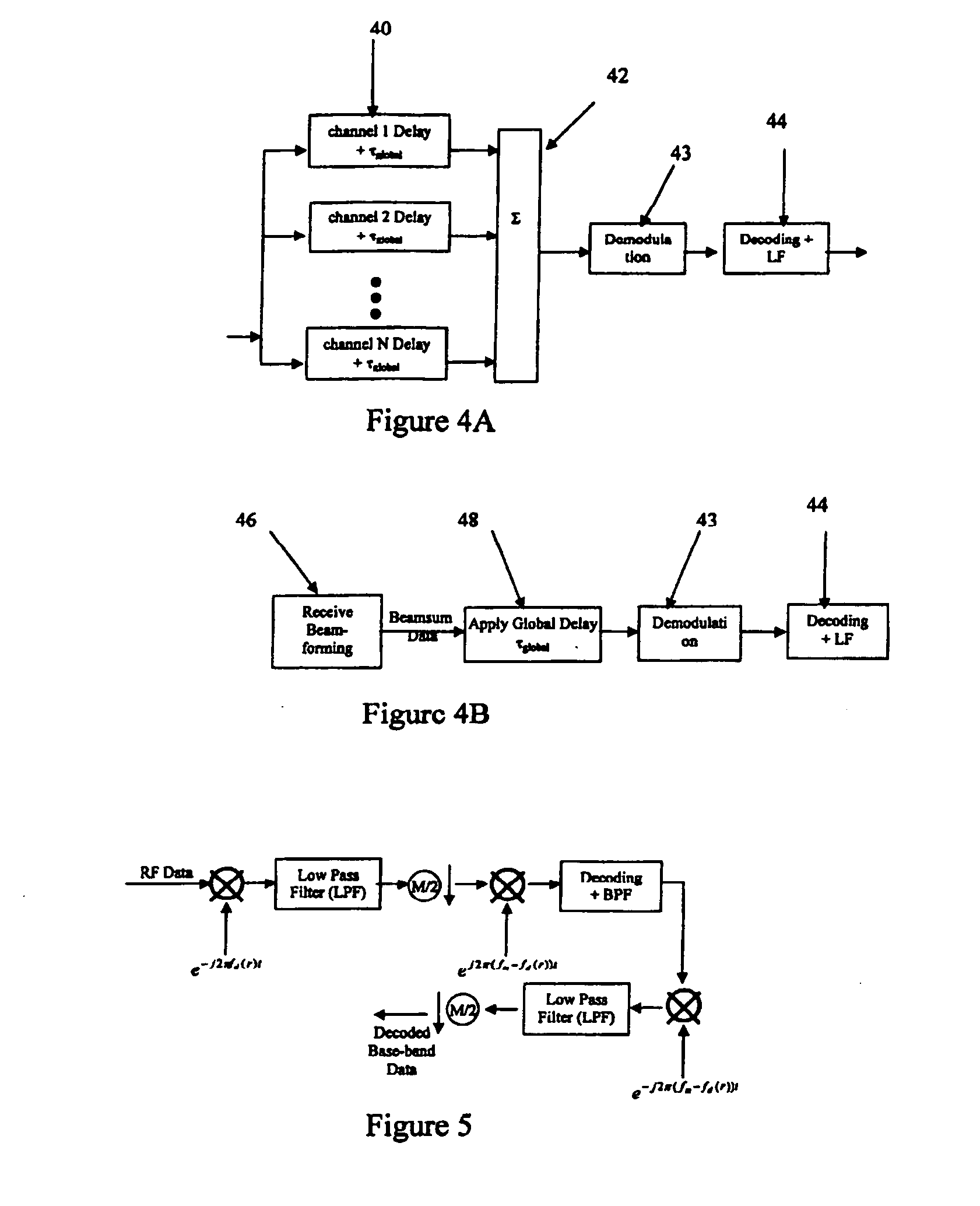
[0018] Coded excitation pulses improve motion (e.g., fluid flow or tissue motion) imaging. A wide-band frequency-modulated or other coded pulse insonifies an object. The pulse is transmitted along the same position inside the object for at least two times, and a set of echo signals are received. A receive filter, such as a matched filter, decodes the received signals. A clutter filter removes information from stationary objects or objects associated with flow or tissue motion. An autocorrelator estimates the motion parameters such as power, velocity and variance. Using the coded excitation pulses, a large time-bandwidth product provides axial resolution and sensitivity improvements. A depth-dependent delay offset corrects for range mis-registration. A depth-dependent velocity estimator compensates for the center frequency downshift. The mis-registration and the frequency downshift are caused by frequency-depend...
PUM
 Abstract
Description
Claims
Application Information