
Amplitude modulator

a modulator and amplitude technology, applied in the direction of modulation, amplitude demodulation, digital transmission, etc., can solve the problems of large power consumption, large linearity constraints on the output stage amplifier, and the smallest bandwidth possible for the radio frequency carrier modulation by which information is transmitted

Active Publication Date: 2007-02-22
KOTAB DOMINIC
View PDF17 Cites 5 Cited by
  • Summary
  • Abstract
  • Description
  • Claims
  • Application Information

AI Technical Summary

Benefits of technology

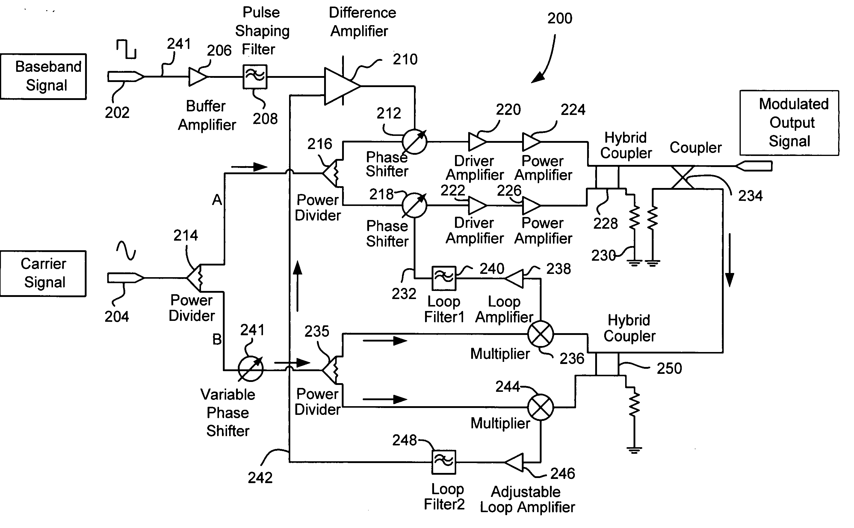
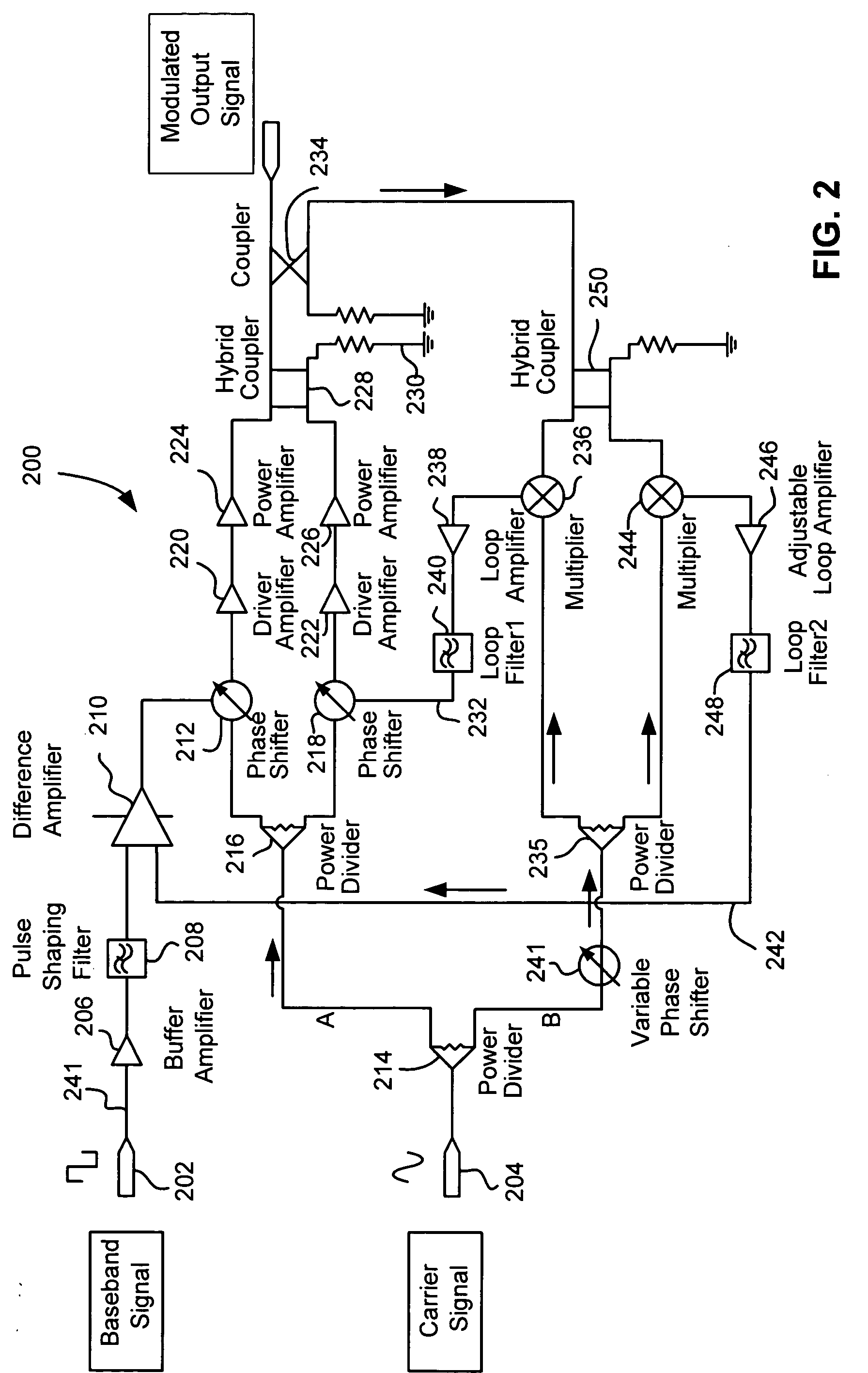
[0010] To provide the aforementioned desirable benefits, a circuit for amplitude modulating a carrier signal includes a carrier signal input, circuitry for splitting the carrier signal into first and second paths, circuitry for phase modulating the carrier signal on the first path, circuitry for phase modulating the carrier signal on the second path, and circuitry for combining the phase modulated carrier signal on the first path with the phase modulated carrier signal on the second path for generating an amplitude modulated output signal.
[0012] To reduce a residual phase variation of the amplitude modulated output signal, a first feedback loop couples the amplitude modulated output signal to the circuitry for phase modulating the carrier signal on the second path. The first feedback loop is coupled to the carrier signal input, where the first feedback loop locks the phase of the amplitude modulated output signal to the carrier signal.

Problems solved by technology

These applications, however, pose two special problems.
First, the Radio Frequency (RF) carrier modulation by which information is transmitted must demand the smallest bandwidth possible due to the general shortage of available spectrum.
Amplifying the modulated carrier without excessive distortion in the transmitter output stage imposes significant linearity constraints on the output stage amplifier.
Class A RF amplifiers provide a distortion-free output, but require large amounts of power.
Unfortunately, these amplifiers are very nonlinear and introduce substantial amplitude distortion.
As with any portable device, second only to reliability in importance is power consumption.
However, the distortion inherent in non-linear amplifiers has been a barrier to use of class B and class C amplifiers in portable RFID transmitters.

Method used


Image

  • Amplitude modulator
  • Amplitude modulator
  • Amplitude modulator

Examples


Embodiment Construction

[0020] The following description is the best mode presently contemplated for carrying out the present invention. This description is made for the purpose of illustrating the general principles of the present invention and is not meant to limit the inventive concepts claimed herein. Further, particular features described herein can be used in combination with other described features in each and any of the various possible combinations and permutations.

[0021] In the drawings, like and equivalent elements are numbered the same throughout the various figures.

[0022] The following specification describes a nonlinear amplifier driven, low phase noise amplitude modulator with virtually no residual phase shift. The amplitude modulator is particularly adapted to implementation in or as a class C operated device which exhibits low power consumption but does not exhibit the distortion traditionally found in class C devices.

[0023] Many types of devices can take advantage of the embodiments d...


PUM


Abstract

A circuit for amplitude modulating a carrier signal includes a carrier signal input, circuitry for splitting the carrier signal into first and second paths, circuitry for phase modulating the carrier signal on the first path, circuitry for phase modulating the carrier signal on the second path, and circuitry for combining the phase modulated carrier signal on the first path with the phase modulated carrier signal on the second path for generating an amplitude modulated output signal. Feedback loops virtually eliminate residual phase shift and make the amplitude modulated output signal linearly proportional to the baseband signal.

Description

FIELD OF THE INVENTION [0001] The present invention relates to Radio Frequency (RF) signal processing circuitry, and more particularly, this invention relates to an energy efficient amplitude modulator exhibiting low phase noise and low residual phase shift. BACKGROUND OF THE INVENTION [0002] Wireless communication systems have become increasingly popular. These applications, however, pose two special problems. First, the Radio Frequency (RF) carrier modulation by which information is transmitted must demand the smallest bandwidth possible due to the general shortage of available spectrum. As a result, both the amplitude and the phase (i.e., frequency) of the carrier must be precisely controlled during modulation. Amplifying the modulated carrier without excessive distortion in the transmitter output stage imposes significant linearity constraints on the output stage amplifier. [0003] Second, the power efficiency of the transmitter is very important where the transmitting end of the...

Claims


Application Information

Patent Timeline
IPC IPC(8): H03D1/00
CPCH03C1/04H03C1/50H03C2200/0079
Inventor ZHOU, LIMINGKIKIN, VADIM
Owner KOTAB DOMINIC
Learn More