Apparatus and methods for rapidly bringing a scanning mirror to a selected deflection amplitude at its resonant frequency

a scanning mirror and resonant frequency technology, applied in electrographic process apparatus, instruments, printing, etc., can solve the problems of large size of mirror system, large amount of power during operation, and large amount of power used in operation, and achieve the effect of greater duty cycle and deflection amplitud

Inactive Publication Date: 2007-02-22
TEXAS INSTR INC
View PDF4 Cites 30 Cited by
  • Summary
  • Abstract
  • Description
  • Claims
  • Application Information

AI Technical Summary

Benefits of technology

[0011] According to the present invention, at start up, first energy drive pulses are generated and applied to the torsional hinged oscillating device to cause the structure to start oscillating. As a result of other features of the invention, these initial drive pulses can have a greater duty cycle than has been typically used in the prior art systems at start up. The frequency of the first drive pulses is then continuously increased and / or decreased through a range of frequencies that includes the resonant frequency of the device. As the frequency of the oscillating device approaches resonance, the deflection amplitude will significantly increase until the sensor indicates a first selected deflection amplitude has been reached. Typically, to avoid damage to the torsional hinges, the first selected deflection amplitude is less than the desired operational deflection amplitude. When the deflection amplitude reaches the first selected value, application of the energy drive pulse is interrupted for a few cycles to allow the oscillation to settle into the resonant frequency of the device. The resonant frequency is then determined by any suitable manner, and second energy drive pulses are generated and applied to the oscillating structure. The second energy drive pulses are substantially at the resonant frequency of the device and may have a smaller duty cycle than the first energy drive pulses. The duty cycle of the second energy drive pulses is then adjusted until the deflection amplitude reaches an operational deflection amplitude value.
[0012] In the event of transient events, controller failures, etc. that could damage the torsional hinges or failure of the controlling circuitry, the second energy drive pulses are turned off until the deflection amplitude decreases to a safe level.

Problems solved by technology

Unfortunately, rotating polygon mirrors must be manufactured to very tight tolerances and rotated at a precise speed so that each facet of the polygon mirror reflects a scanning laser beam in a consistent manner.
These strict requirements result in a mirror system that is bulky, expensive, and that uses a substantial amount of power during operation.
However, when the device or mirror returns to its central position, it overshoots the center position and continues in the opposite direction.
Unfortunately, if the deflection amplitude becomes too large, the hinges may be overstressed to the point that they shatter and destroy the oscillating device or mirror.
For example, the Young's modulus of silicon varies over temperature such that for a MEMS type pivotally oscillating device made of silicon, clamping the device in a package such that it is restrained in the hinge direction will cause stress in the hinges as the temperature changes.
This in turn will lead to drift in the resonant frequency of the pivotal oscillations.
Since applications that use a pattern of light beam scans, such as laser printing and projection imaging require a stable and precise drive to provide the signal frequency and scan velocity, the changes in the resonant frequency and scan velocity of a pivotally oscillating mirror due to temperature variations can restrict or even preclude the use of the device in laser printers and scan displays.
Further, as was mentioned above, if the stress loading is increased above the maximum acceptable levels for a given rotational angle, the reliability and operational life of the device can be unacceptably reduced or dramatically ended by shattered hinges.

Method used


Image

  • Apparatus and methods for rapidly bringing a scanning mirror to a selected deflection amplitude at its resonant frequency
  • Apparatus and methods for rapidly bringing a scanning mirror to a selected deflection amplitude at its resonant frequency
  • Apparatus and methods for rapidly bringing a scanning mirror to a selected deflection amplitude at its resonant frequency

Examples


Embodiment Construction

[0024] The making and using of the presently preferred embodiments are discussed in detail below. It should be appreciated, however, that the present invention provides many applicable inventive concepts that can be embodied in a wide variety of specific contexts. The specific embodiments discussed are merely illustrative of specific ways to make and use the invention, and do not limit the scope of the invention.

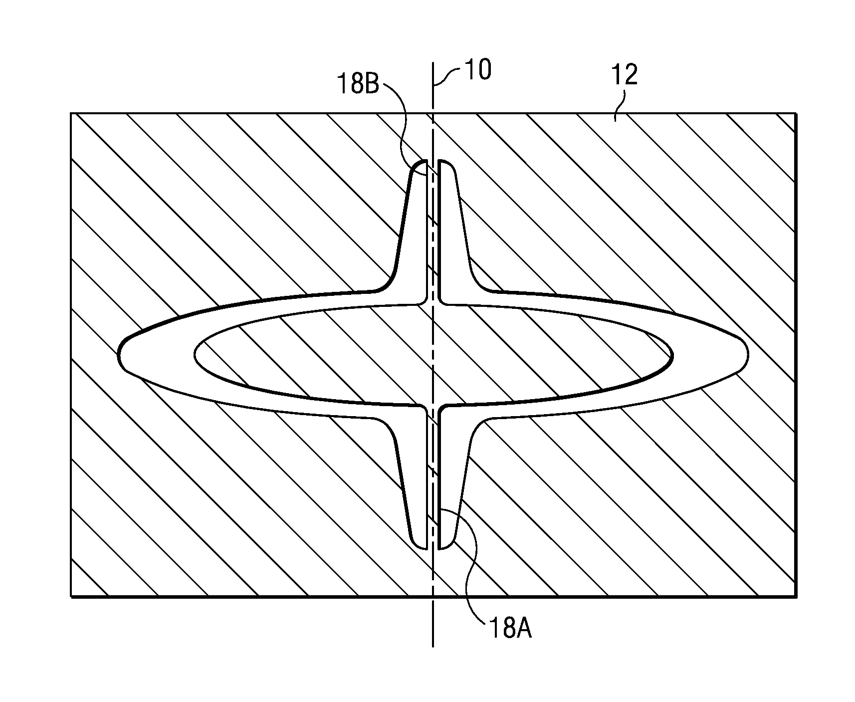
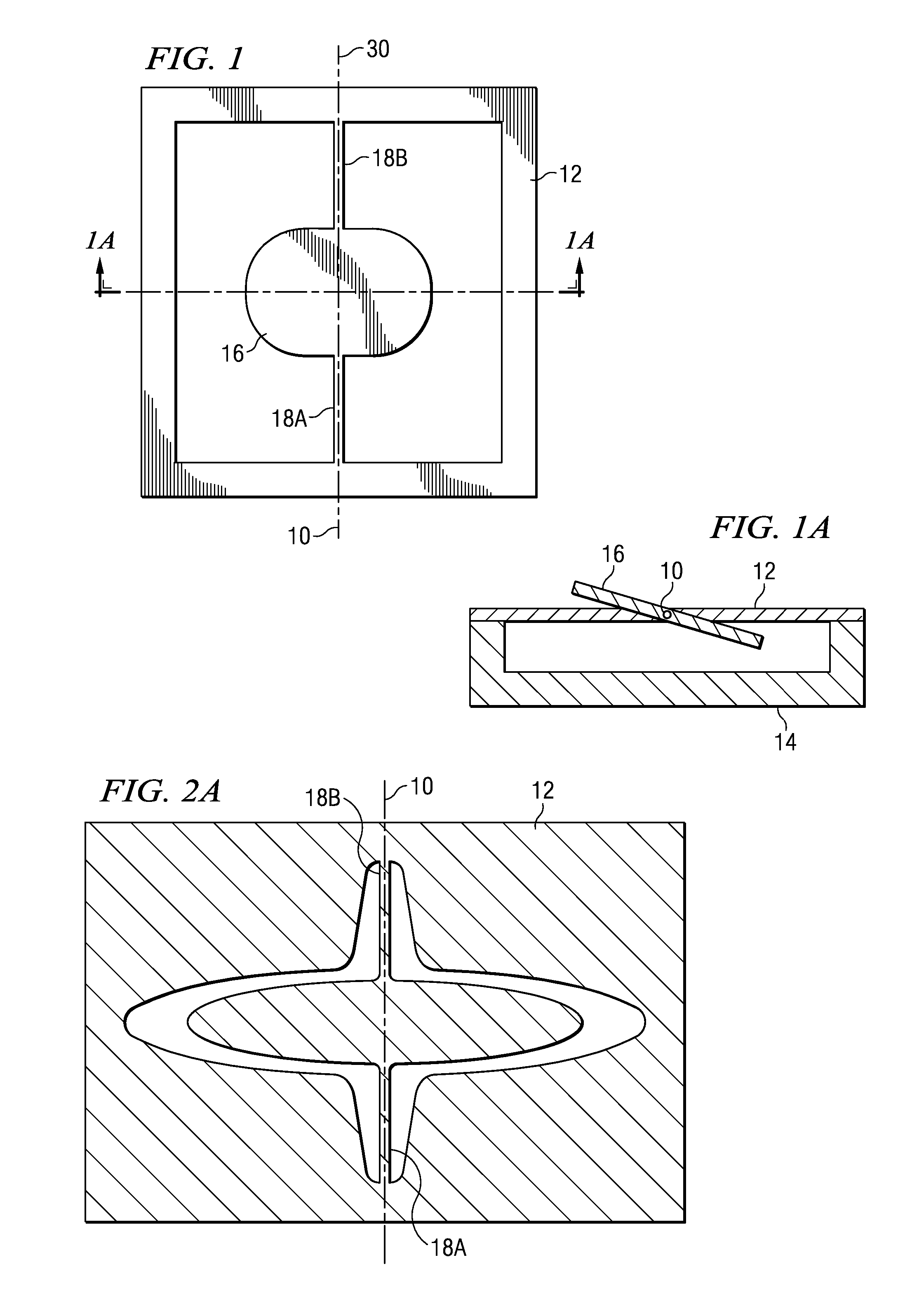
[0025] Like reference numbers in the figures are used herein to designate like elements throughout the various views of the present invention. The figures are not intended to be drawn to scale and in some instances, for illustrative purposes, the drawings may intentionally not be to scale. One of ordinary skill in the art will appreciate the many possible applications and variations of the present invention based on the following examples of possible embodiments of the present invention. The present invention relates to a torsional hinged structure or apparatus with a movea...


PUM


Abstract

The present invention provides methods and apparatus for rapidly starting or bringing an oscillating device to its resonant frequency, and operating deflection amplitude. The invention is particularly applicable for use with an oscillating mirror used as the scanning engine of a laser printer. Control circuitry of the oscillating device first determines the resonant frequency of the device and then adjusts or increases the duty cycle of successive energy drive pulses until a selected deflection amplitude is reached. Energy drive pulses at the resonant frequency of the device and the adjusted duty cycle are then provided to maintain oscillation of the device. In a laser printer, a single sensor is used to determine the deflection amplitude of the resonant beam sweep by determining the spacing or timing between a pair of the sensors pulses.

Description

[0001] This application claims the benefit of U.S. Provisional Application No. 60 / 653,168, filed on Feb. 14, 2005, entitled Deflection Controller For A Resonant Scanning Mirror, which application is hereby incorporated herein by reference.TECHNICAL FIELD [0002] The present invention relates generally to the field of torsional hinge MEMS scanning devices such as mirrors, and more particularly to methods and apparatus for rapidly bringing the scanning device to a selected deflection amplitude and to the resonant frequency at start up. The method and apparatus of the invention is also useful for maintaining the selected deflection amplitude and resonant frequency even in the event of temperature changes, large transients signals or a controller failure that could cause damage to the mirror. BACKGROUND [0003] The use of rotating polygon scanning mirrors in laser printers to provide a beam sweep or scan of the image of a modulated light source across a photosensitive medium, such as a ro...

Claims


Application Information

Patent Timeline
Patent Type & Authority Applications(United States)
IPC IPC(8): G02B26/08
CPCG02B26/0841G02B26/101G02B26/105G03G2215/0404H04N1/053H04N1/1135H04N2201/04755B41J2/471G03G15/0435
Inventor HEMINGER, MARK DAVIDNOXON, JAMES EUGENE
Owner TEXAS INSTR INC
Why Eureka
Try Eureka