Fan housing with strain relief

Inactive Publication Date: 2007-02-22
EBM PAPST ST GEORGEN & -
View PDF14 Cites 141 Cited by
  • Summary
  • Abstract
  • Description
  • Claims
  • Application Information

AI Technical Summary

Benefits of technology

[0005] It is an object of the present invention to prov

Problems solved by technology

This is because such leads are usually soldered onto a circuit board of the motor, and this soldered join cannot carry loads over the long ter

Method used


Image

  • Fan housing with strain relief
  • Fan housing with strain relief
  • Fan housing with strain relief

Examples


Embodiment Construction

[0017] In the description hereinafter, the terms “left,”“right,”, “upper,” and “lower” refer to the respective Figure of the drawings. Identical or identically functioning parts are labeled with the same reference characters in the various Figures, and are usually described only once.

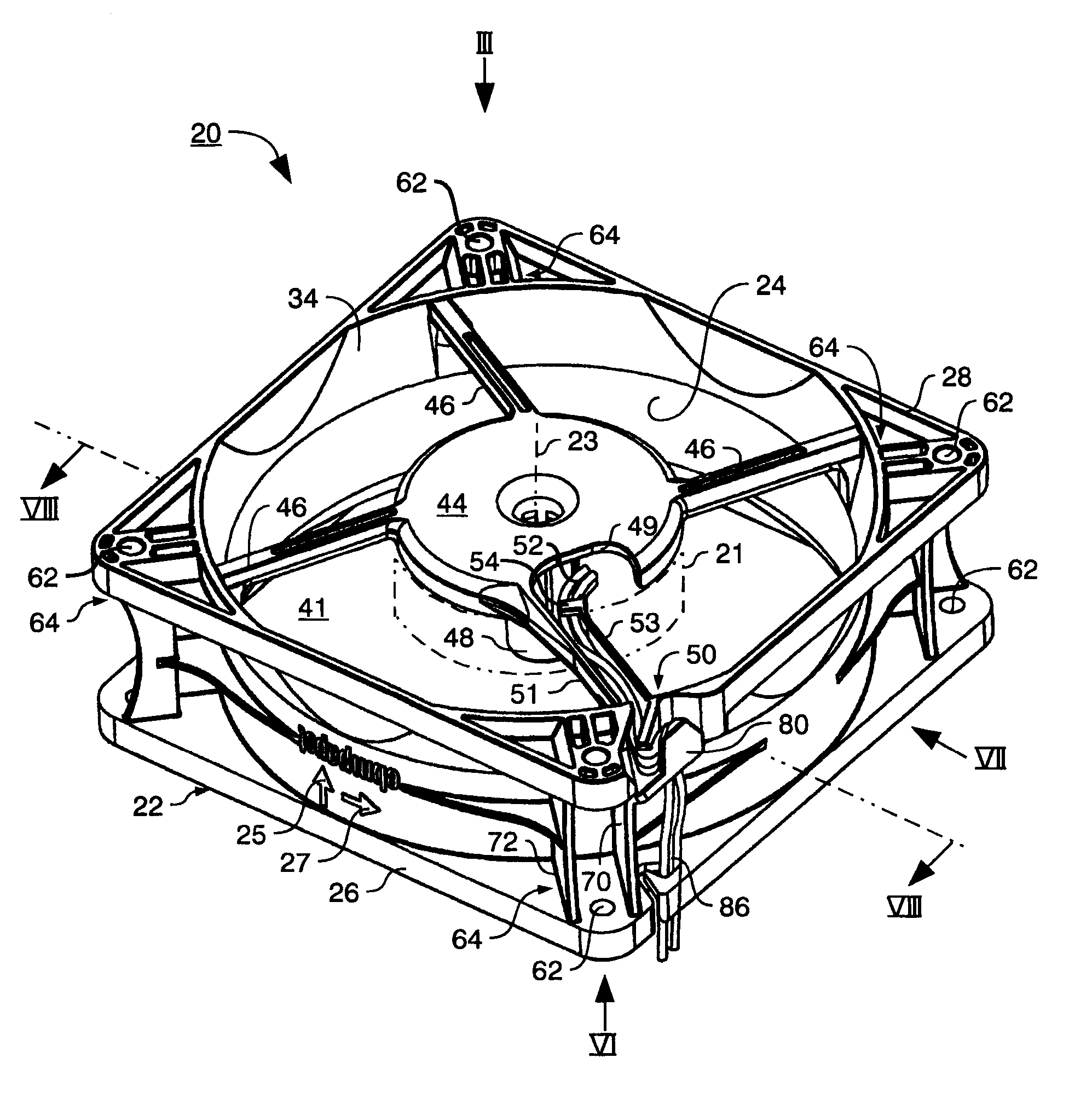
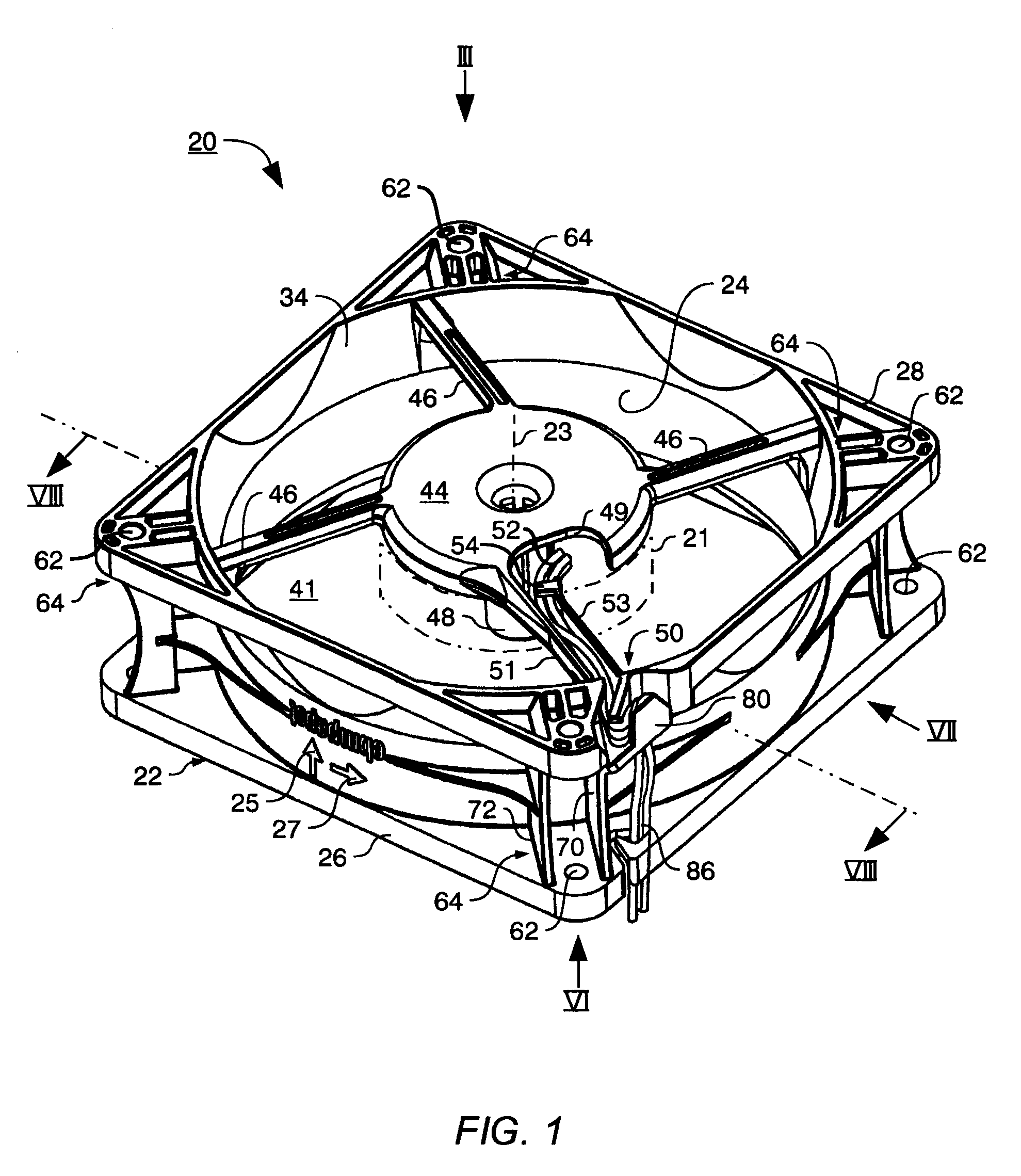
[0018]FIG. 1 is a three-dimensional depiction of an equipment fan 20 that is depicted here as an axial fan. The invention is not, however, limited to axial fans. It can instead be used in the same fashion in other types of fan, e.g. in diagonal and radial fans.

[0019] Fan 20 has a fan housing 22 that is approximately in the shape of a cylindrical tube 24 and is provided with a mounting flange 26 at its lower (in FIG. 1) end and a mounting flange 28 at its upper end. The air flow-through direction 25 is defined by an inflow side and an outflow side. FIG. 1 shows the outflow side, labeled 34, at the top.

[0020] Fan 20 has a motor 21 to drive fan blades 40 (FIG. 3) that are arranged, rotatably about a rot...


PUM


Abstract

An equipment fan has a housing (22) that externally defines an air passage opening (41) provided in the fan (20). The fan has a motor (21) for rotatably driving blades (40) about a rotation axis (23), as well as a carrier element (51), provided between the motor (21) and the housing (22), which extends transversely to the passage (41) and is configured as a trough (53) that serves to receive an electrical lead (52) and guides the lead along a predetermined path from the motor (21) to a location (64) on the housing (22). The fan also has a deflection device (50) which, by deflecting the lead (52) at a first deflection location (55) and at a second deflection location (84) and in at least two planes extending at a predetermined angle with respect to one another, effects strain relief for the lead (52) that proceeds to the motor (21).

Description

CROSS-REFERENCE [0001] This application claims priority from my German application DE 20 2005 013 419.8, filed 19 Aug. 2005, the entire content of which is hereby incorporated by reference. FIELD OF THE INVENTION [0002] The invention relates to a fan, in particular to an equipment fan, having a fan housing and having a motor for driving fan blades that are arranged rotatably in an air passage opening provided in the fan, and having an electrical connection that leads from the motor to a housing part, and comprises at least one electrical lead that is usually in the form of a stranded conductor. BACKGROUND [0003] So-called strain-relief must be provided for such leads. This is because such leads are usually soldered onto a circuit board of the motor, and this soldered join cannot carry loads over the long term and can be damaged or destroyed by mechanical tension; such mechanical tension must therefore be stopped before it reaches the circuit board. [0004] WO 2004 / 046 557 and corresp...

Claims


Application Information

Patent Timeline
IPC IPC(8): H02K7/00H02K11/00H02K5/00
CPCF04D25/0613F04D29/526F04D25/0693
Inventor FLEIG, ARMIN
Owner EBM PAPST ST GEORGEN & -
Why Eureka
Try Eureka