Single hand operated adjustable carrying device and method of use thereof

Inactive Publication Date: 2007-03-01
LAUSELL EMILIANO
View PDF16 Cites 11 Cited by
  • Summary
  • Abstract
  • Description
  • Claims
  • Application Information

AI Technical Summary

Benefits of technology

[0026] One of the gripping plates joins the lower portion of the levers while the handle assembly joins the upper portion of the levers. The guide track of the second gripping member, and along which the bushing of the first gripping member spins and slides, is positioned between the levers of the first gripping member. The dual torsion spring assembly includes a cross member biased by a pair of torsion springs against the levers when the levers are pivotally moved downwards below the teeth, unlocking the adjustable carrying device. This allows the slidi

Problems solved by technology

This is true even when studies show that many job related back injuries result from the application of improper or excessive effort during the performance of such tasks.
However, in some instances, the devices are awkward to operate, requiring additional time or effort from the part of the end user.
In other instances, the devices are invasive to the object's surfaces and their use would compromise the object's integrity or aesthetics.
This teeth positioning under the package lends itself to be difficult and awkward.
In addition, the height of the package to be lifted is limited to that of the physical length of the jaw levers.
However, the metal teeth on the convex curvature of the jaw's inner surface provide an extremely limited contact surface area between the device and the battery.
Substantial pressure must be concentrated at these contact points in order to hold the battery, greatly increasing the possibili

Method used


Image

  • Single hand operated adjustable carrying device and method of use thereof
  • Single hand operated adjustable carrying device and method of use thereof
  • Single hand operated adjustable carrying device and method of use thereof

Examples


Embodiment Construction

—FIGS. 1 THROUGH 5A—PREFERRED EMBODIMENT

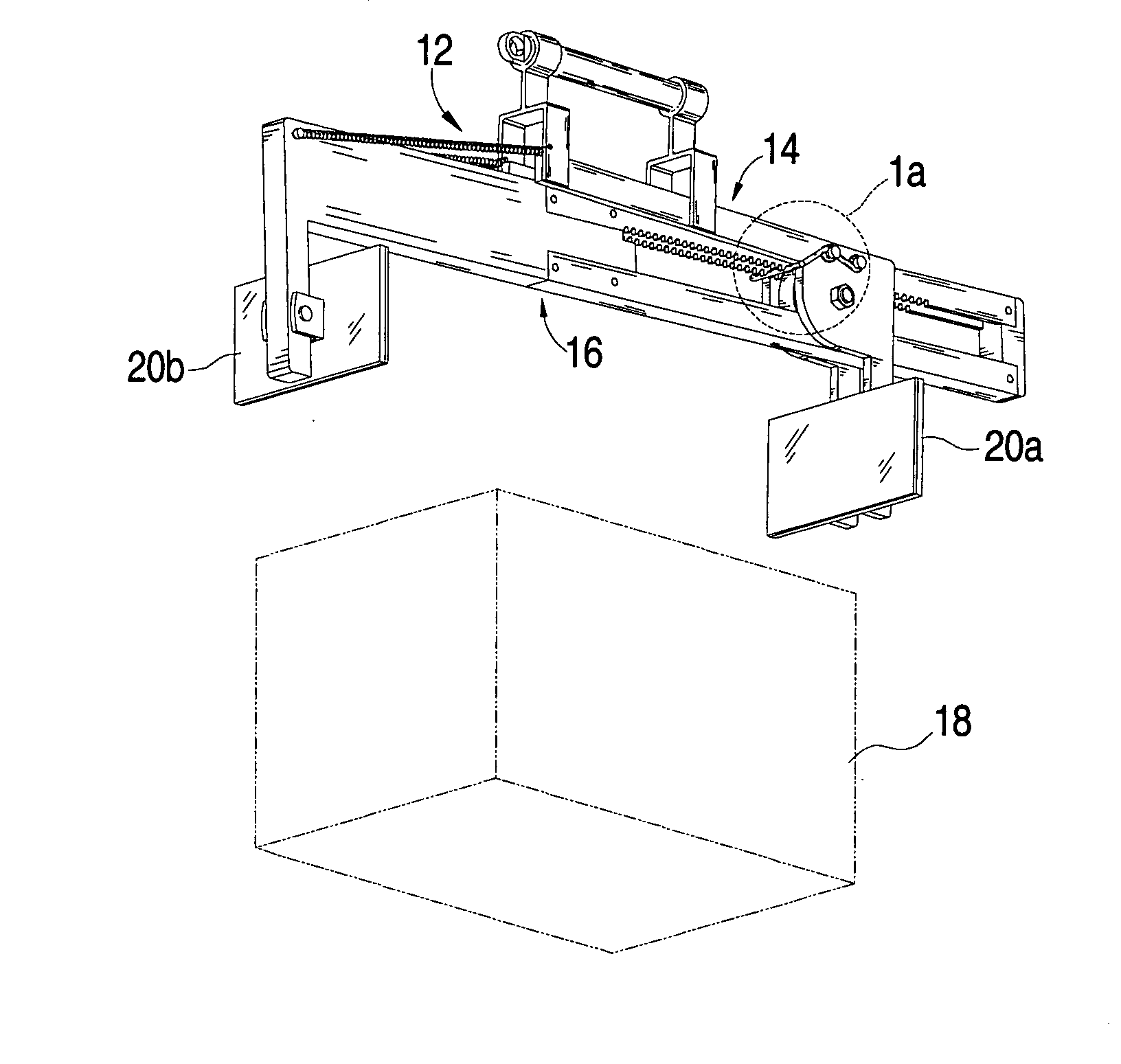
[0065] As shown in the drawings for purposes of illustration, the present invention is concerned with an adjustable carrying device, generally referred to by the reference number 12, which allows the use of a single human hand in the gripping, lifting and carrying of objects having opposed parallel surfaces and generally requiring both human arms and hands to be carried.

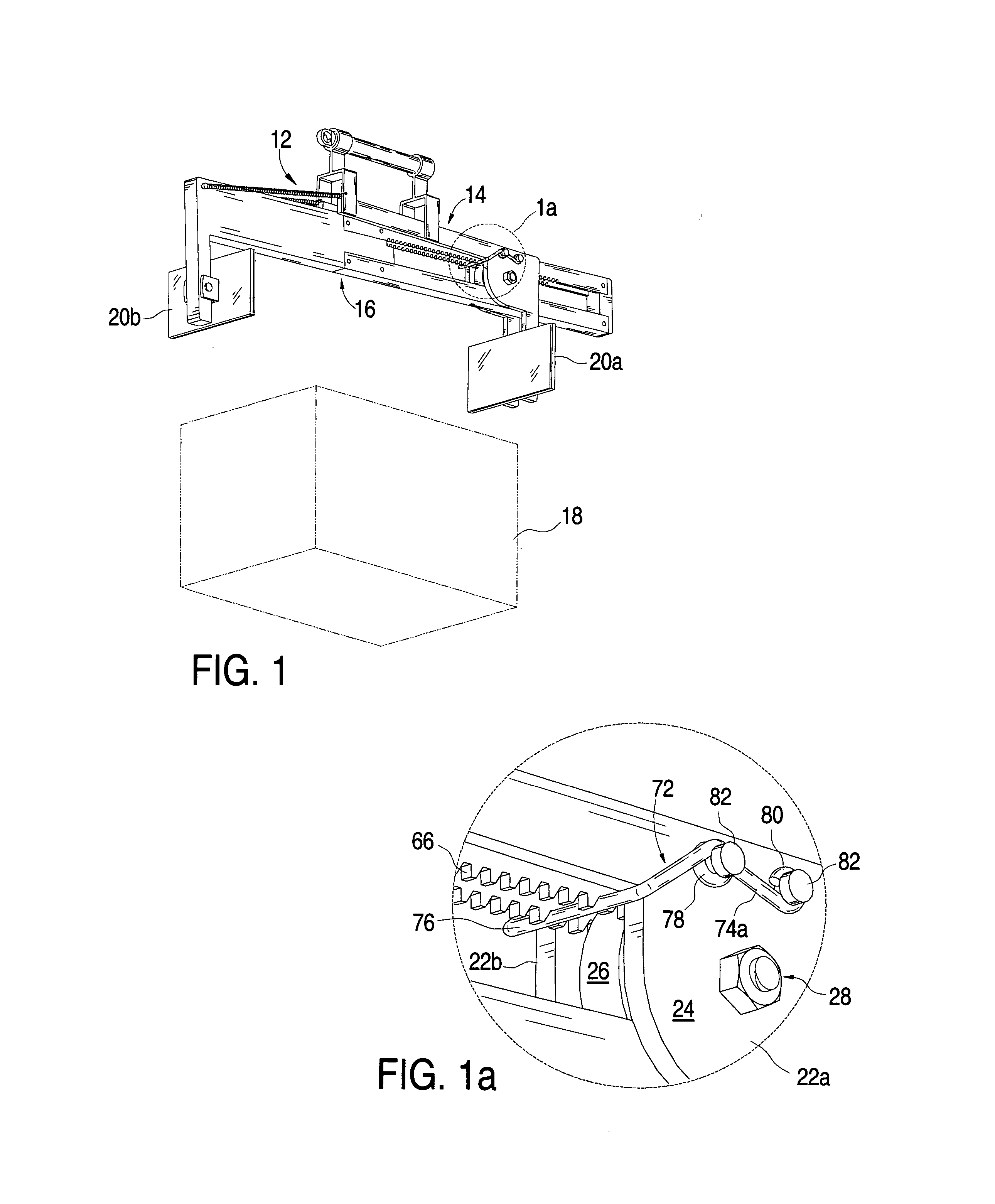
[0066] With reference to FIG. 1, the adjustable carrying device 12 comprises a first and a second gripping member 14 and 16, pivotally and slidably connected to each other for engaging object 18 between gripping plates 20a and 20b.

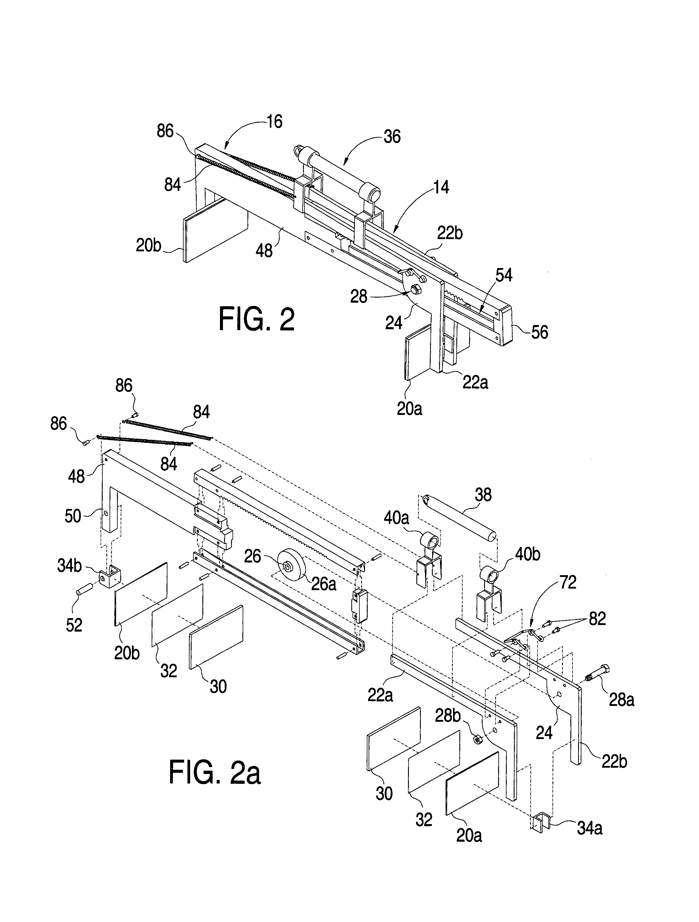
[0067] As shown in FIGS. 2 and 2a, first gripping member 14 comprises a pair of substantially L-shaped levers 22a and 22b cut from a sheet of rigid material (e.g., metal). Each lever has a horizontally disposed first end, a vertically disposed second end and a web 24 diagonally extending intermediate of, and further joining, both ends. Levers 22a an...


PUM


Abstract

An adjustable carrying device (12) includes a pair of gripping members (14, 16) in a slip joint pivot connection having a handle assembly (36) and gripping plates (20a, 20b) for grasping and handling an object. A pivotally activated/deactivated locking mechanism includes a plurality of evenly spaced teeth (66) within a guide track (54) and a cross member (76) biased between lock and unlock positions by a pair of torsion springs (74a, 74b). A pair of levers (22a, 22b) moved in unison by handle assembly (36) activate and deactivate the locking mechanism. While in unlock position a pair of coil tension springs (84) assist in the single handed adjustment of the gripping plates against the object's opposed surfaces. A subsequent upward pivotal motion of handle assembly (36) activates the locking mechanism, forcing gripping plates (20a, 20b) towards each other, firmly gripping the object prior to its lift.

Description

BACKGROUND OF THE INVENTION [0001] 1. Field of Invention [0002] This invention relates to single hand operated load carrying devices, specifically those having a pair of gripping jaws. [0003] 2. Prior Art [0004] Of all the ancient tasks performed by humans, the employment of both human arms and hands in the grasping, lifting and carrying of objects having opposed parallel surfaces is probably one of the oldest. Even in our modern times, product distribution and delivery needs require an endless list of items to be packaged in containers meant to be carried by hand. These items include consumable goods, appliances, medicines, food, apparel, liquids, mail etc. [0005] The manual lifting and transporting of these packages is a task built into the design of work stations and handling procedures found in common workplace. This is true even when studies show that many job related back injuries result from the application of improper or excessive effort during the performance of such tasks....

Claims


Application Information

Patent Timeline
IPC IPC(8): B65G7/12
CPCB65G7/12
Inventor LAUSELL, EMILIANO
Owner LAUSELL EMILIANO
Why Eureka
Try Eureka