Ankle-foot orthosis device

a technology for ankles and feet, applied in chiropractic devices, medical science, physical therapy, etc., can solve problems such as inability to achieve dorsiflexion assist moments, inability to bend the knee,

Inactive Publication Date: 2007-03-01
UNIVERSITY OF DELAWARE
View PDF14 Cites 12 Cited by
  • Summary
  • Abstract
  • Description
  • Claims
  • Application Information

AI Technical Summary

Problems solved by technology

Both of these disorders are due to the weakness of the tibialis anterior muscle which results in lack of dorsiflexion assist moment.
If there is a weak push-off, the stride length reduces, and the gait velocity fails.
Hyperactive or weak dorsiflexors may result in insufficient dorsiflexion, which must be compensated for by alterations in the gait patterns so that the toes do not drag.
In addition to the toes dragging, the foot may become abnormally supinated, which may result in an ankle sprain or fracture, when the weight is applied to the limb.
While inversion-eversion motion in all of these orthoses is accommodated through the flexibility of the material, such as polypropylene, the limitation in normal inversion-eversion does not provide a natural motion to the ankle and adds discomfort.

Method used


Image

  • Ankle-foot orthosis device
  • Ankle-foot orthosis device
  • Ankle-foot orthosis device

Examples


example 1

Kinematics Model for Ankle-Foot Motion

[0039] In this example, the motion of the ankle is modeled based on two degrees-of-freedom. The first degree-of-freedom is a rotation in the vertical plane about an axis (Z1) passing through the ankle joint. This axis is known as the dorsiflexion-plantarflexion (D / P) motion axis. The second degree-of-freedom is a rotation about an axis (Z2). This motion is known as inversion-eversion (I / E) motion. For this model, segments of the foot are assumed to be rigid links, and the dorsiflexion-plantarflexion and inversion-eversion motions are approximated by revolute joints.

[0040] The orientations of the two joint axes considered in this study are shown in FIG. 6, which shows the projection of the joint axes in the frame attached to the leg shank (X0, Y0, Z0). The axis Z0 represents the knee joint axis. This projection is taken when the foot is resting firmly on the ground and the leg is perpendicular to the ground.

[0041] The Denavit-Hartenberg (DH) ...

example 2

Measuring Forces and Torques Applied at the Dorsalflexion-Plantarflexion and Inversion-Eversion Joints

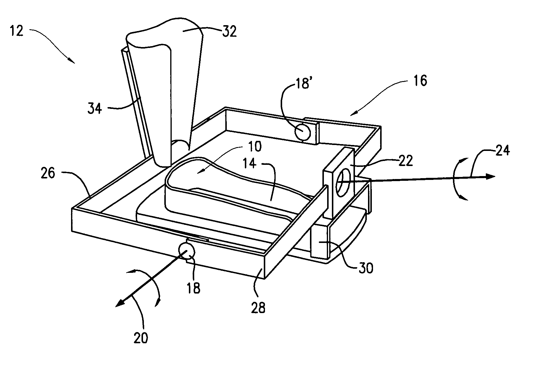
[0044] In measuring the forces and torques at the revolute joints of the orthosis, a Newton-Euler analysis can be used to convert the raw force-torque sensor and encorder data into joint forces and torques. When using telescopic joints on the orthosis, the device can be adjusted to allow the axes of the device to coincide with the axes of the human motion. The device then moves largely synchronously with little or no relative motion compared to the subject's ankle and foot. The device can be adjusted until the subject is able to execute the normal motion of the foot. Perfect alignment between the human and device axes can be difficult, but there are several techniques to facilitate adequate agreement. The device and the subject's ankle and foot are kept largely fixed.

[0045] The free body diagram shown in FIG. 7 illustrates five bodies contributing to this kinematics model. The fi...

example 3

Experimental Data Collected During Motion of the About the DIP Joint

[0053] Experimental results were obtained using a device in accordance with the present invention. Experiments were performed with a healthy subject who was asked to perform primarily motion about the D / P joint. Exemplary orientations of the D / P and I / E frames are shown in FIG. 4. The frames are placed at the actual joint in the human foot. The orientation information is useful in interpreting the collected data. The subject performed dorsiflexion-plantarflexion motion without contacting the foot to the ground. The ranges of rotation obtained are shown in FIG. 8. The range of motion during foot movement about the D / P axis was about 0.5 rad around the D / P axis and about 0.15 rad around the I / E axis. It can be seen that the frequency of motion is around 1 Hz, or one revolution of the joint per second. FIG. 9 presents the forces and torque applied by the subject about the D / P joint during the motion around the D / P ax...


PUM


Abstract

An ankle-foot orthosis comprising a leg member 12; a foot member 14; a frame 16 connecting the leg member to the foot member, wherein the frame comprises a first revolute joint 18 that rotates about a first axis 20 and a second revolute joint 22 that rotates about a second axis 24, wherein the first and second axes are non-parallel. The frame can further comprise a foot member segment 30 secured to the foot member 14 and extending to the second revolute joint 22. The orthosis can comprise a first force-torque sensor 36 located on the leg member, a second force-torque sensor 38 located on the foot member, and an encoder positioned on one of the revolute joints. The invention includes a method of measuring ankle-foot-related forces comprising positioning a subject's leg and foot in an ankle-foot orthosis; collecting data from the first and second force-torque sensors; and analyzing the collected data to determine the motion of the subject's ankle.

Description

CROSS REFERENCE TO RELATED APPLICATIONS [0001] This application claims the benefit of U.S. Provisional Application No. 60 / 690,857, filed Jun. 15, 2005, the contents of which are incorporated herein by reference.RELATED FEDERALLY SPONSORED RESEARCH [0002] The work described in this application was sponsored by the following Federal Agencies: NIH, grant number 1R01 HD38582001A2.FIELD OF THE INVENTION [0003] The present invention is directed to an ankle-foot orthosis device. More particularly, the invention is directed to an improved ankle-foot orthosis device providing two degrees-of-freedom motion, specifically addressing both inversion-eversion and dorsiflexion-plantarflexion. BACKGROUND OF THE INVENTION [0004] An ankle-foot orthosis (AFO) is commonly used to help subjects with weakness of ankle dorsiflexor muscles due to peripheral or central nervous system disorders. Both of these disorders are due to the weakness of the tibialis anterior muscle which results in lack of dorsiflexi...

Claims


Application Information

Patent Timeline
Patent Type & Authority Applications(United States)
IPC IPC(8): A61F5/00
CPCA61F5/0127A61F2005/0134A61F2005/0132
Inventor AGRAWAL, SUNILAGRAWAL, ABHISHEKBANALA, SAIBINDER-MACLEOD, STUART
Owner UNIVERSITY OF DELAWARE
Why Eureka
Try Eureka