

Vehicle driving assist system
a technology for driving assistance and vehicles, applied in the direction of process control, pedestrian/occupant safety arrangement, instruments, etc., can solve the problem that the system is not able to aggressively urge the host vehicle to accelera
- Summary
- Abstract
- Description
- Claims
- Application Information
AI Technical Summary
Problems solved by technology
Method used
Image

Examples
first embodiment
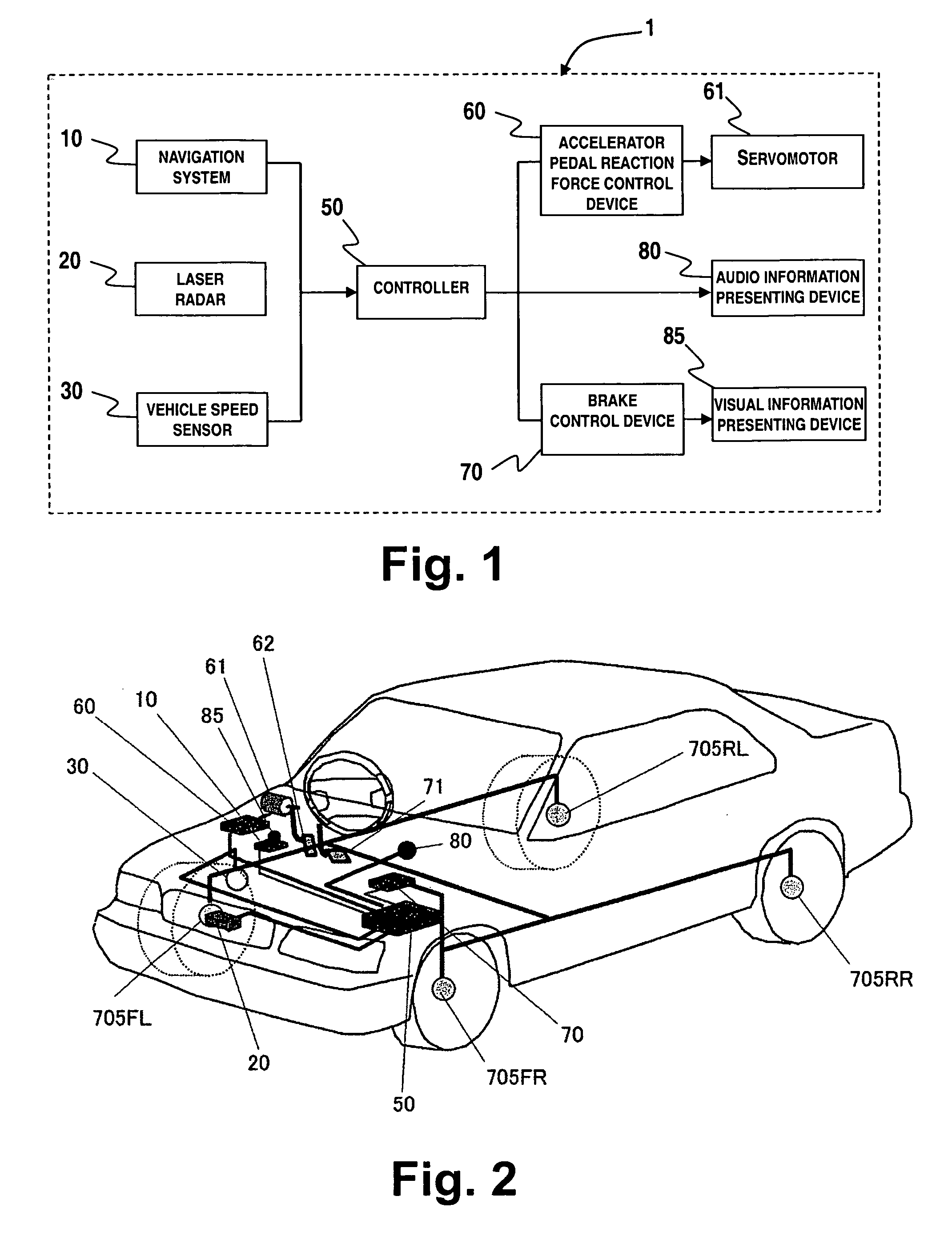
[0040] Referring initially to FIG. 1, an on-board vehicle driving assist system is illustrated in accordance with a first embodiment of the present invention. FIG. 1 is a block diagram of a vehicle driving assist system in accordance with the first embodiment of the present invention. FIG. 2 is a schematic perspective view of a vehicle (hereinafter also called “the host vehicle”) in which the vehicle driving assist system shown in FIG. 1 is installed in accordance with the first embodiment of the present invention. With the present invention, as explained below, the vehicle driving assist system conveys a risk potential of a vicinity of surrounding the host vehicle to the driver by manipulating the actuation reaction force that is exerted by a driver-operated driving operation device of the host vehicle when the driving operation device is operated. Additionally, deceleration can be more aggressively urged in an effective manner when deceleration of the host vehicle is necessary by ...
second embodiment
[0123] A vehicle driving assist system in accordance with a second embodiment of the present invention will now be explained. FIG. 17 is a system diagram of the vehicle driving assist system 2 in accordance with the second embodiment. In FIG. 17, parts having the same functions as the parts of the first embodiment shown in FIGS. 1 and 2 are indicated with the same reference numerals. The second embodiment will be explained chiefly by describing its differences with respect to the first embodiment.
[0124] As shown in FIG. 17, the vehicle driving assist system 2 includes an active suspension device 90. The active suspension device 90 is configured to control the hydraulic pressure of hydraulic cylinders installed between each of the wheels and the host vehicle body and thereby control changes in the attitude of the host vehicle body. In this embodiment, a controller 50A controls the active suspension device 90 in such a manner as to give the driver a sensation of deceleration that dri...
third embodiment
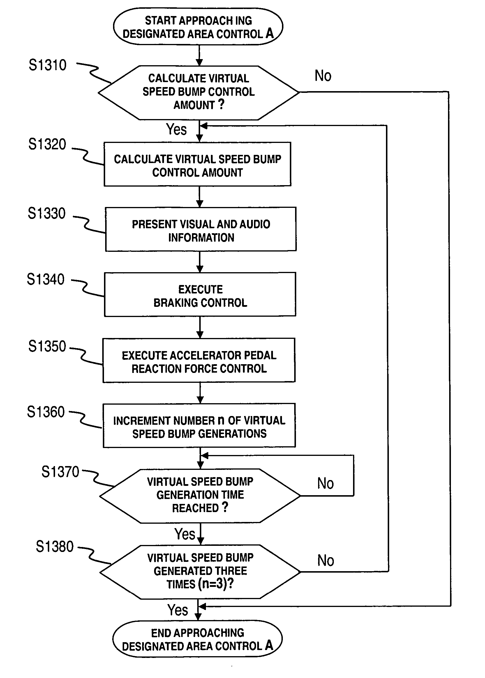
[0157] A vehicle driving assist system in accordance with a third embodiment of the present invention will now be explained. The basic constituent features of a vehicle driving assist system in accordance with the third embodiment are the same as those of the first embodiment shown in FIGS. 1 and 2. The third embodiment will be explained chiefly by describing its differences with respect to the first embodiment.
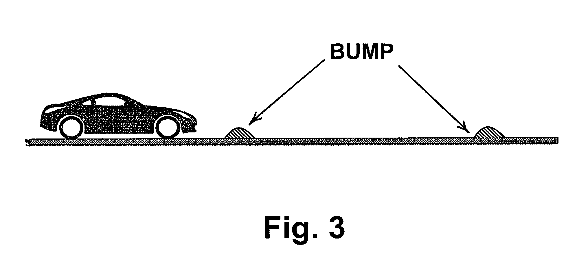
[0158] In the third embodiment, when the host vehicle is traveling in the vicinity of a designated area or inside a designated area, the system executes a virtual speed bump control to cause the host vehicle to decelerate in such a manner as to mimic the behavior the host vehicle would exhibit if it were crossing over a speed bump (i.e., to generate an imaginary speed limiting road protrusion) and a constant deceleration control to cause the host vehicle to decelerate at a constant rate as though it were traveling up an ascending road (slope). As shown in FIG. 25, the consta...
PUM
 Abstract
Description
Claims
Application Information