Storage control device and separation-type storage device

a storage control and storage device technology, applied in the field of storage control devices and separation-type storage devices, can solve the problems of increasing the use material of communication lines, reducing the service life of the communication line, and requiring a long time for data transfer

Inactive Publication Date: 2007-03-01
HITACHI LTD
View PDF12 Cites 32 Cited by
  • Summary
  • Abstract
  • Description
  • Claims
  • Application Information

AI Technical Summary

Problems solved by technology

However, when a communication line is used, the bandwidth and speed of the communication line differ depending on the data size or the like of the copy target, and the data transfer requires a long time.
When a plurality of dedicated high-speed communication lines are used, the data transfer time can also be shortened, but the usage material of the communication lines increases and the running costs rise.
However, the data write speed and data read speed of the tape device are slow in compariso...

Method used


Image

  • Storage control device and separation-type storage device
  • Storage control device and separation-type storage device
  • Storage control device and separation-type storage device

Examples


example 1

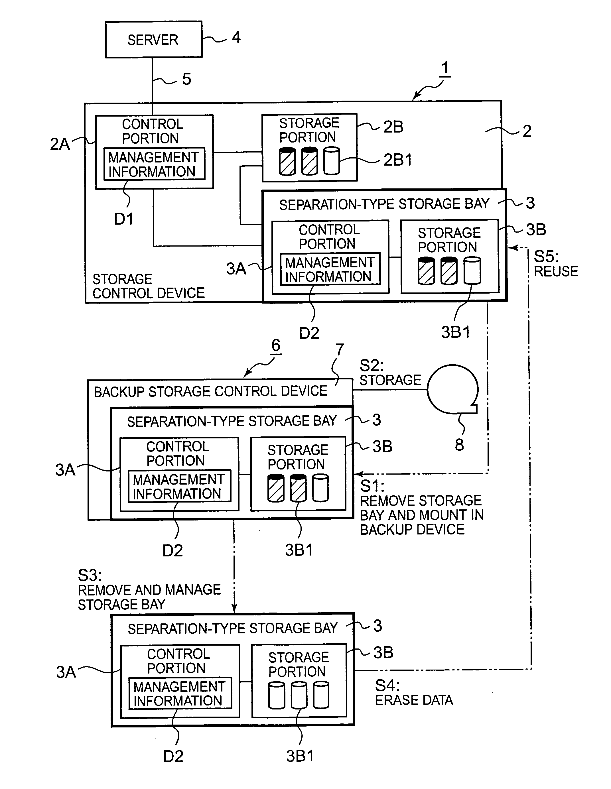
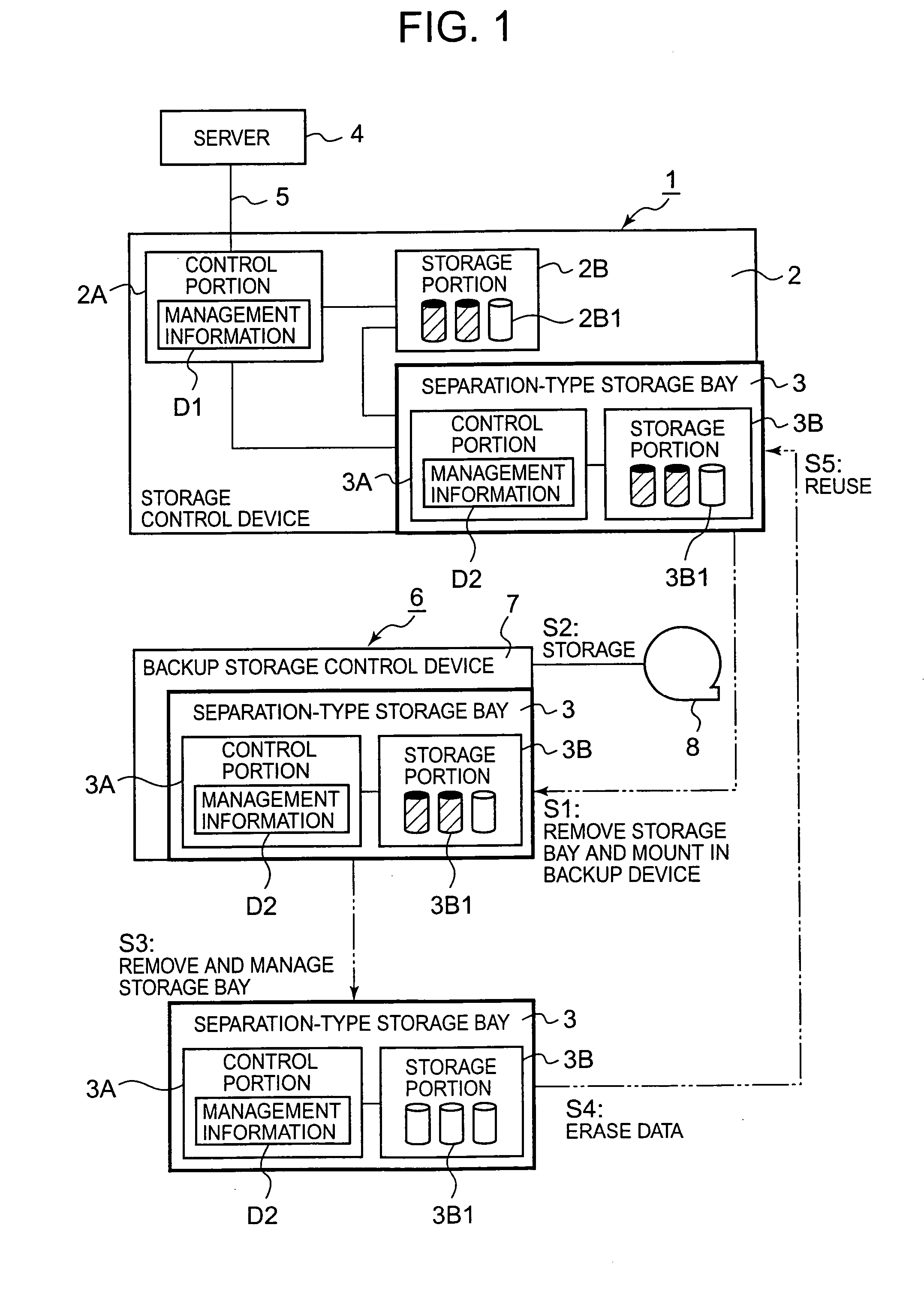
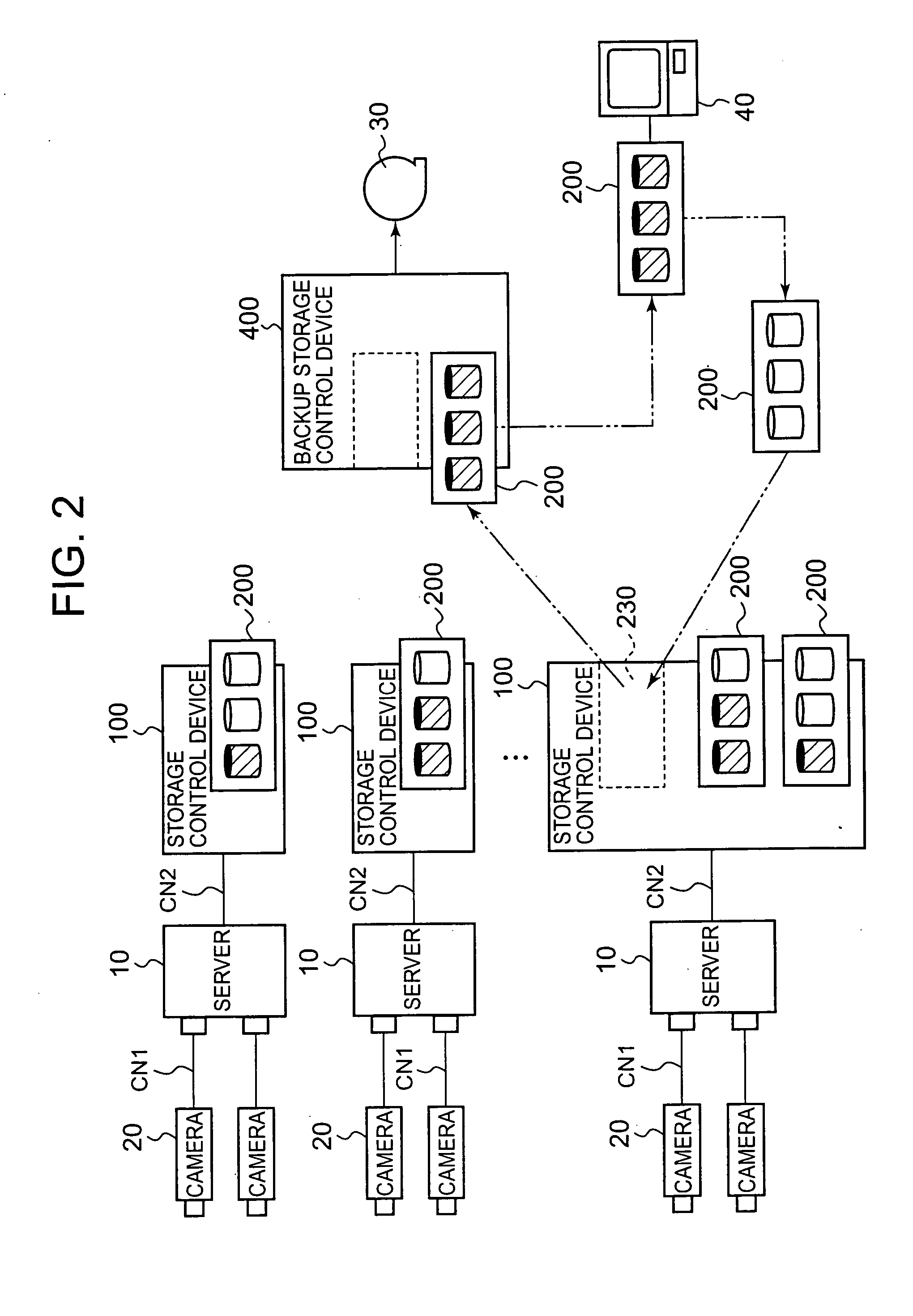
[0079]FIG. 2 is a perspective view showing the overall configuration of a storage system that uses the storage control devices 100 and 400 according to the present invention. This storage system is used as a part of the monitoring system, for example. When the relationship of correspondence with FIG. 1 is described first, a server 10 corresponds with server 4 in FIG. 1, the storage control device 100 corresponds with the storage control device 1 in FIG. 1, the separation-type storage bay 200 corresponds with the separation-type storage bay 3 in FIG. 1, the backup storage control device 400 corresponds with the backup storage control device 6 in FIG. 1, and the backup device 30 corresponds with the backup device 8 in FIG. 1.

[0080] A surveillance camera 20 is installed on each floor of the building, a plurality of stores, and in a plurality of offices. Each surveillance camera 20 images the scenery of the physical world in predetermined cycles and outputs the image data to the server...

example 2

[0200] A second example will be described on the basis of FIG. 27. In this example, after initial construction at the backup site is complete, update data issued by the primary site is transferred to the backup site via a communication network CN3.

[0201]FIG. 27 is an explanatory view of the overall configuration of the storage system of this example. A primary storage control device 100A is installed at the primary site. Backup data of a regular volume that the primary storage control device 100A comprises is copied to the separation-type storage bay 200. The separation-type storage bay 200 storing the backup data is introduced to the backup site.

[0202] A secondary storage control device 100B is provided at the backup site. The separation-type storage bay 200 is attached to the secondary storage control device 100B and backup data in the separation-type storage bay 200 is copied to the regular volume in the secondary storage control device 100B. As a result, the initial constructi...


PUM


Abstract

According to the present invention, a portion of the storage control device is configured as a detachable separation-type storage bay and a large volume of data can be moved altogether by transporting the storage bay. The separation-type storage bay is detachably provided in the device main body of the storage control device. The storage bay comprises a plurality of disk drives. When a backup of the primary volume is created, a secondary volume is created in the storage bay and data is copied. The storage bay is removed from the device main body by the user and attached to a backup storage control device. The backup storage control device recognizes the storage configuration of the storage bay by acquiring management information when the storage bay is attached to the backup storage control device. The backup storage control device reads the backup data from the storage bay and stores the backup data in the backup device.

Description

CROSS-REFERENCE TO RELATED APPLICATIONS [0001] This application relates to and claims priority from Japanese Patent Application No. 2005-251196 filed on Aug. 31, 2005, the entire disclosure of which is incorporated herein by reference. BACKGROUND OF THE INVENTION [0002] 1. Field of the Invention [0003] The present invention relates to a storage control device and separation-type storage device. [0004] 2. Description of the Related Art [0005] The storage control device is able to provide a host computer (‘host’ hereinbelow) with high-capacity and high-performance storage services. In a storage control device, for example, a multiplicity of disk drives is arranged in the form of an array and storage areas are constructed on the basis of RAID (Redundant Array of Independent Disks). A logical volume (LU: Logical Unit) constituting a logical storage area is established on a physical storage area that each disk drive comprises. The host is able to read and write data with respect to the l...

Claims


Application Information

Patent Timeline
IPC IPC(8): G06F13/12
CPCG06F11/1456H04L67/1097G06F11/2015G06F11/1458
Inventor ABE, TETSUYAMUROTANI, AKIRA
Owner HITACHI LTD
Why Eureka
Try Eureka