Load-sensing bearing

a technology of load sensing bearings and bearings, applied in the field of bearings, can solve the problems of not being able to provide the multi-faceted data needed by high-level vdc electronic systems or processor-controlled systems in the rolling mills industry or the machine-tool industry, and not being able to provide signals indicating all loads and torques, high-level vdc electronic devices or other such monitoring devices to function

Inactive Publication Date: 2007-03-08
THE TIMKEN CO
View PDF6 Cites 81 Cited by
  • Summary
  • Abstract
  • Description
  • Claims
  • Application Information

AI Technical Summary

Problems solved by technology

However, the '849 Fujita et al. bearing assembly is unable to provide the multi-faceted data needed by high-level VDC electronic systems or by the processor-controlled systems in the rolling-mills industry or the machine-tool industry.
However, the device disclosed in the '844 Yoshikawa et al. patent cannot provide signals indicating all loads and all torques required to enable a high level VDC electronic device or other such monitoring devices to function properly.
As a result, the signals from the strain gages on the device are unable to detect the forces tending to cause a vehicle to skid sideways or to roll the vehicle over.

Method used


Image

  • Load-sensing bearing
  • Load-sensing bearing
  • Load-sensing bearing

Examples


Embodiment Construction

[0042] The following detailed description illustrates the invention by way of example and not by way of limitation. The description enables one skilled in the art to make and use the invention, and describes several embodiments, adaptations, variations, alternatives, and uses of the invention, including what is presently believed to be the best mode of carrying out the invention.

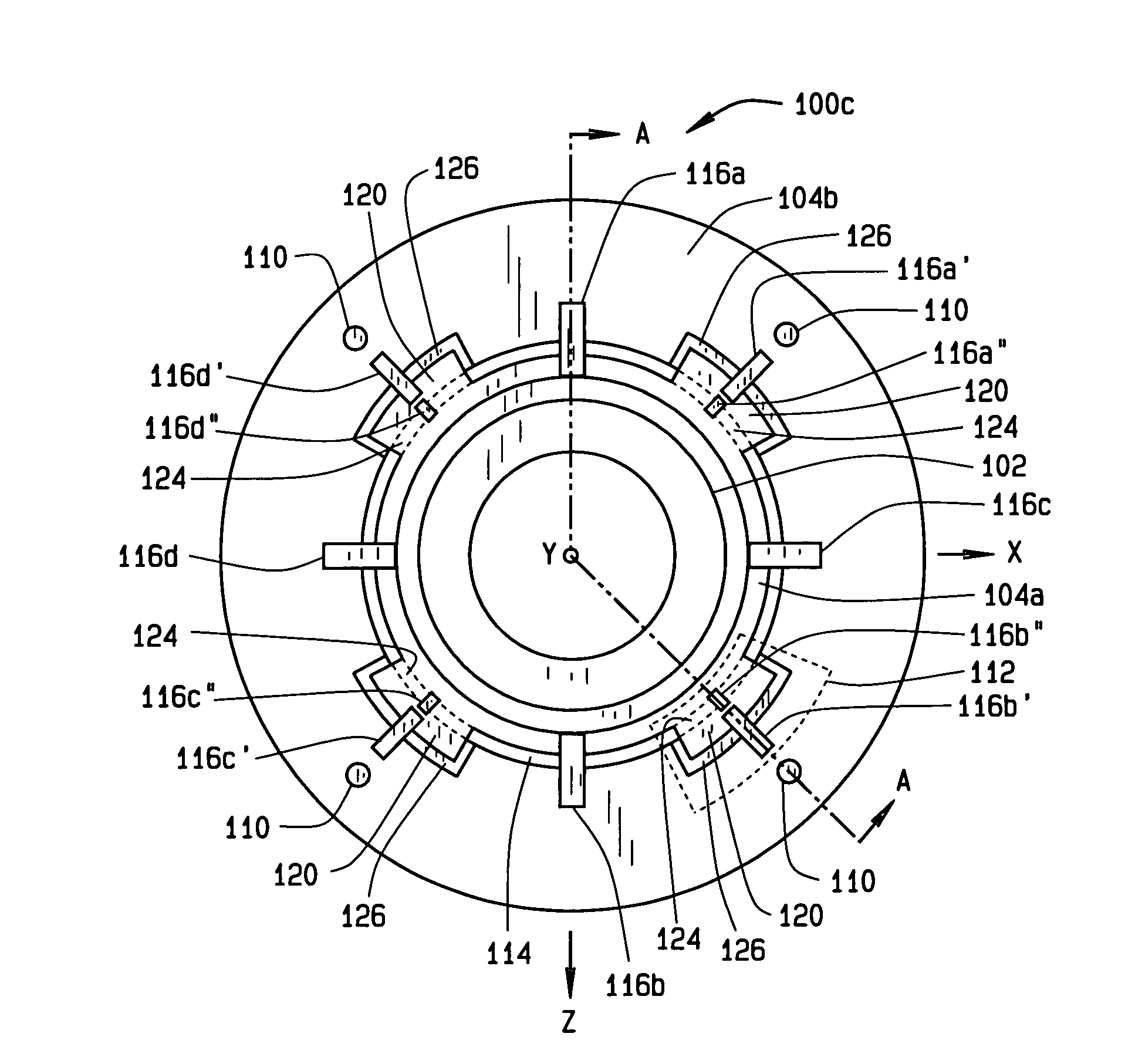
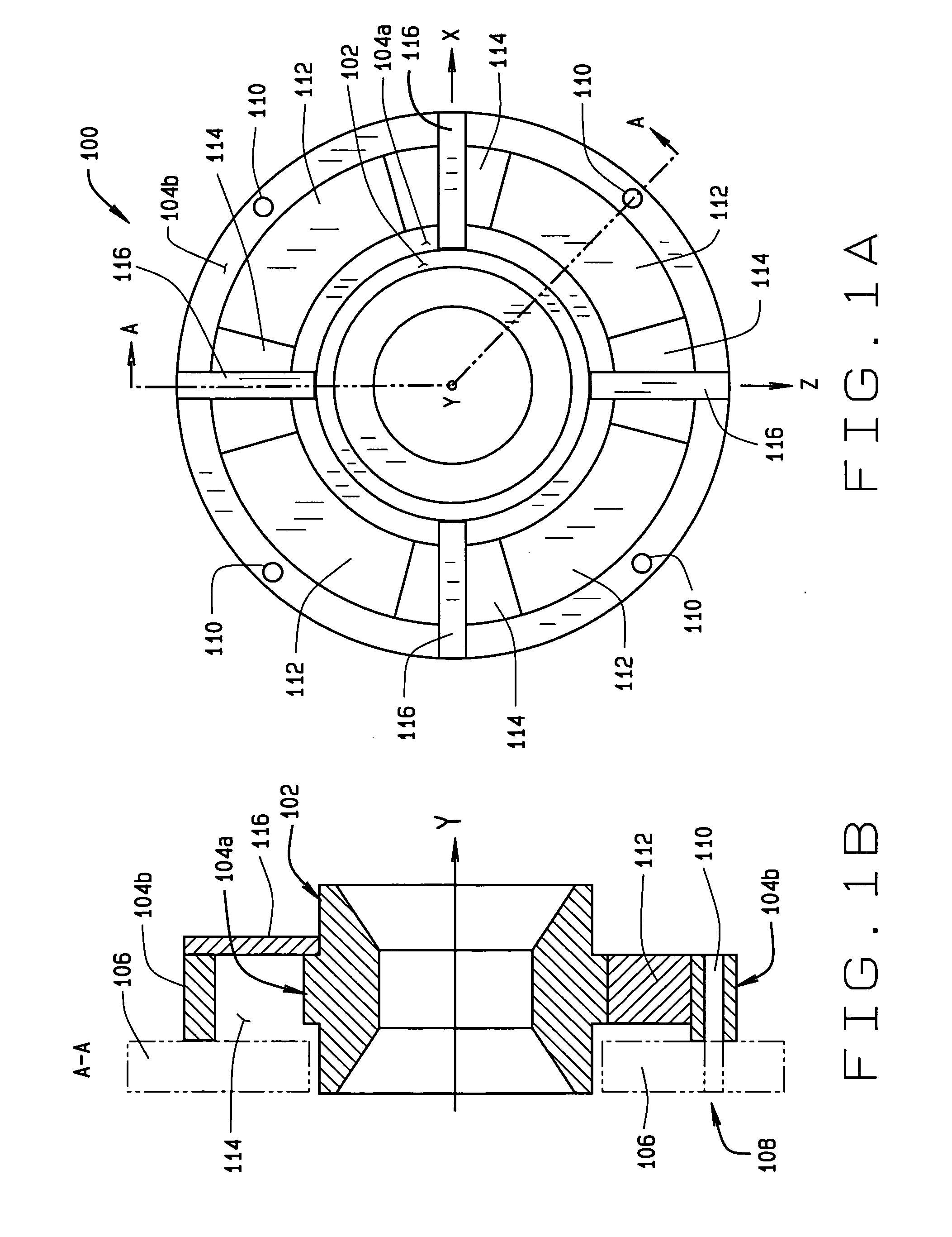
[0043] Turning to the figures, FIGS. 1A and 1B illustrate a general load sensing bearing assembly 100 of the present invention. The load-sensing bearing assembly 100 is generally constructed to support a cone (not shown) and rolling elements (not shown, but which can be any type of rolling elements such as, but not limited to, tapered, cylindrical, ball, needle, or spherical). The load-sensing bearing assembly 100 includes a bearing cup 102 which can assume any orientation about the Y-axis, and a flange assembly 104 for attachment of the bearing cup 102 to an application structure 106 by a suitable number o...


PUM

PropertyMeasurementUnit
forcesaaaaaaaaaa
radial forcesaaaaaaaaaa
thrust forcesaaaaaaaaaa

Abstract

A load sensing bearing assembly comprises a bearing outer race secured to an application structure by a flange assembly incorporating a plurality of anisotropic spring regions which enable a limited range of displacement and/or rotation of the bearing outer race relative to the application structure in response to applied forces or moments. A set of sensor modules disposed through the bearing outer race and flange assembly acquire measurements from which the radial forces, thrust forces, and tilting moments exerted on the bearing outer race can be determined.

Description

CROSS-REFERENCE TO RELATED APPLICATIONS [0001] Not Applicable. STATEMENT REGARDING FEDERALLY SPONSORED RESEARCH [0002] Not Applicable. BACKGROUND OF THE INVENTION [0003] The present invention relates generally to bearings and, in particular to a bearing assembly configured with sensors to monitor applied forces and torques to provide responsive signals for use by devices, which monitor the bearing loads. [0004] The bearing assembly of the present invention may be used to measure radial forces, thrust force, tilting moments, rotation speeds, and temperature at the bearing for use in many applications such as Vehicle Dynamics Control Systems (Vehicle Stability Control Systems), vehicle rollover prevention systems, tire-integrity monitoring systems, road-condition monitoring systems, and vehicle suspension-control systems. [0005] There are a number of applications where the loads and types of loads placed on a bearing assembly in operation can provide significant information about the ...

Claims


Application Information

Patent Timeline
Patent Type & Authority Applications(United States)
IPC IPC(8): G01L3/14
CPCG01L5/161G01L5/0009F16C19/386F16C19/522G01L5/162
Inventor MCDEARMON, GRAHAM
Owner THE TIMKEN CO
Why Eureka
Try Eureka