
Carton with ice retention flaps

Inactive Publication Date: 2007-03-08
MEADWESTVACO PACKAGING SYST LLC
View PDF13 Cites 100 Cited by
  • Summary
  • Abstract
  • Description
  • Claims
  • Application Information

AI Technical Summary

Benefits of technology

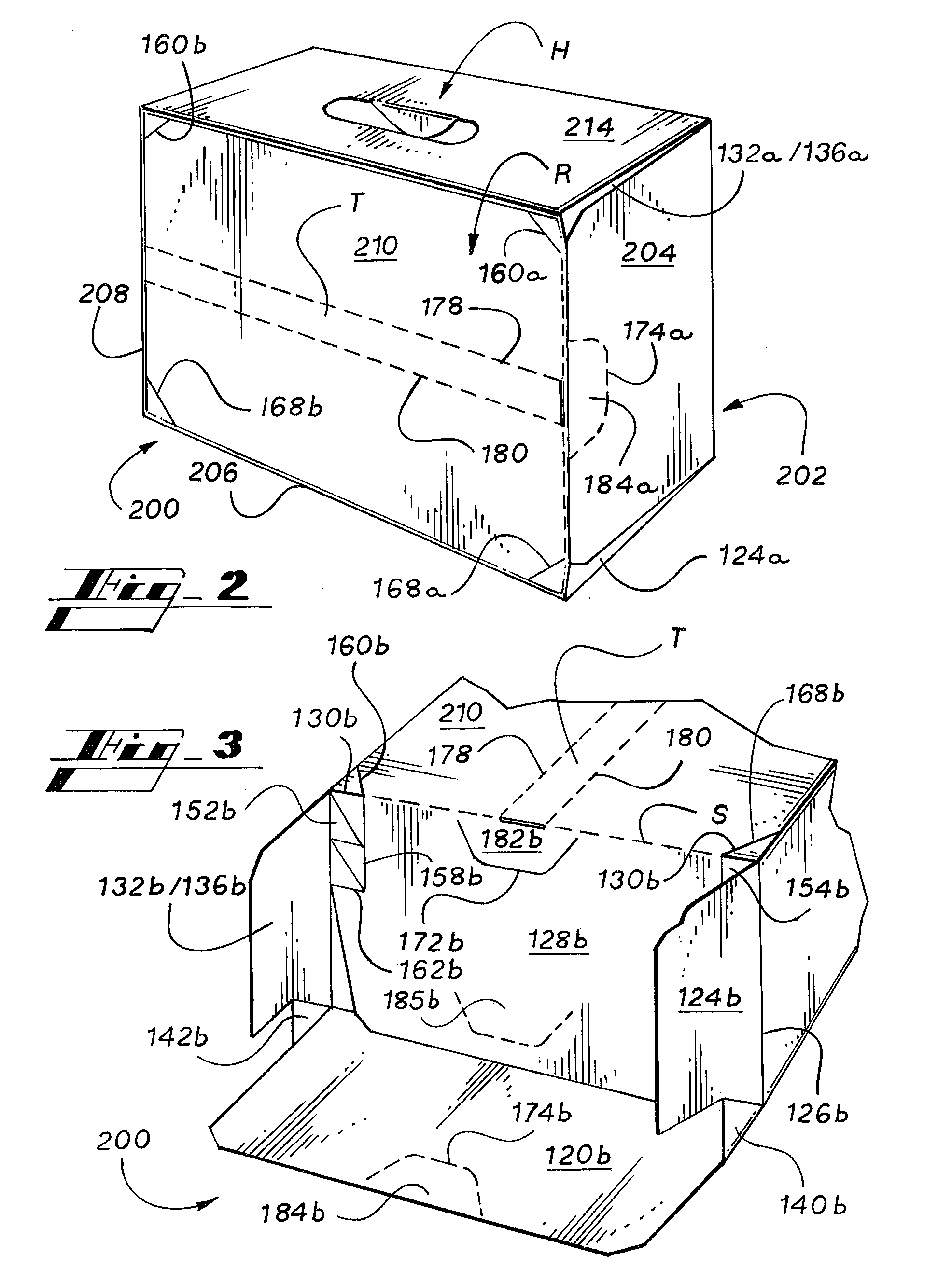
[0005] The various embodiments of the present invention overcome the shortcomings of the prior art by providing a carton or other container that can be configured to enclose articles, such as beverage cans, and then to be opened and reconfigured to form a retaining structure for retaining additional material, such as ice, above or around the articles that are enclosed within the carton. The leak resistant carton is advantageously manufactured as a unitary structure, without requiring substantial expenditures for additional sheet material.
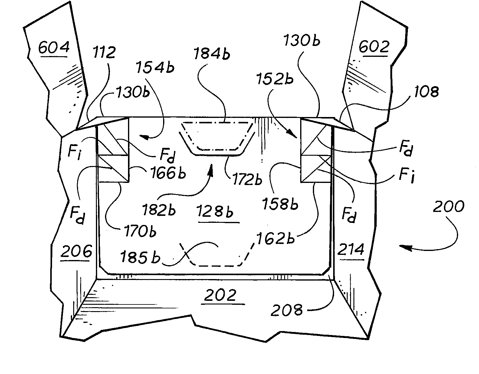
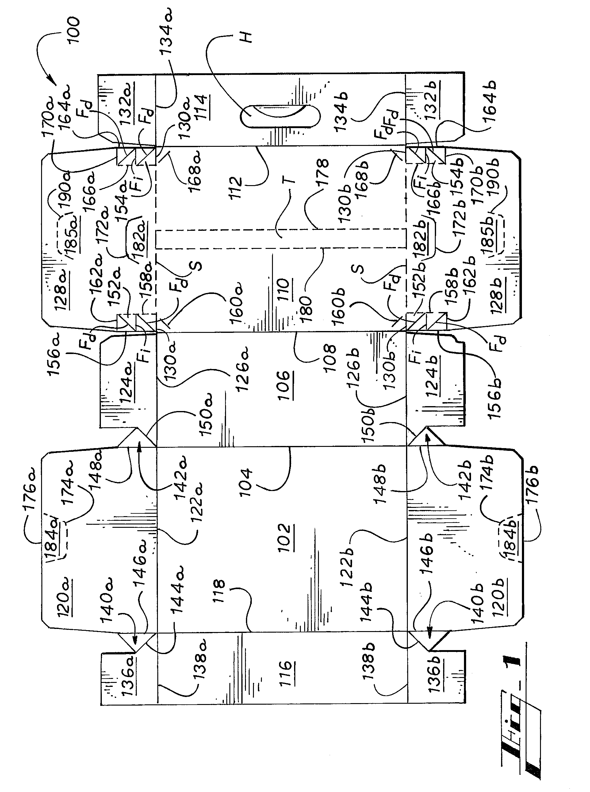
[0006] Generally described, the retaining structure is formed from a wall of the carton which is divisible into retaining panels hingedly connected to opposing vertically disposed walls of the carton so as to be foldably raised into an upright position along the hinged connections, as well as from end flaps or panels that are slidable with respect to other opposed and vertically disposed walls of the carton. Together, the retaining panels and the slidable end flaps approximate a chimney-like structure that effectively extends the height of the peripheral walls of the carton so that additional material can be poured or otherwise placed on top of the articles.
[0008] Each end wall is a composite structure that includes a bottom end flap that is fixedly connected to the bottom and side walls of the carton and a top end flap. It is this top end flap that is slidable with respect to the bottom end flap, which remains fixedly connected as the remnant of the end wall after the carton is opened and the retaining structure is formed. Breaking the second, and third seams frees each of the slidable top end flaps from connection to the remainder of the carton except for a pair of connecting strips that foldably connects each slidable top end flap to an end of each of the side walls and optionally to the retention panels. These connecting strips facilitate a telescoping sliding motion upward of the slidable top end flap with respect to the fixed bottom end flap, in which the top end flap moves from a face contacting arrangement toward a coplanar, edge to edge arrangement with respect to the bottom end flap. In this configuration, the free downward extending edge of the slidable top end flap is moved into closer proximity to, but may continue to partially overlap, the distal upward extending edge of the bottom end flap.
[0010] With the retention flaps and top end flaps raised, a material such as ice can be poured on top of the articles still within the carton, and can be heaped up above the level of the uppermost ends of the articles, and retained by the retaining structure. As the ice melts, web panels that join the bottom end flaps to adjacent side end flaps prevent the liquid from leaking from the bottom corners of the carton. A convenient, disposable, and inexpensive cooler is thereby achieved, the cooler having leak resistant bottom corners.

Problems solved by technology

Regardless of whether such coolers are disposable (e.g., STYROFOAM) or reusable, they create an extra expense and inconveniently must be discarded or transported home.
Cartons have been developed that serve as containers, carriers, and coolers, but such cartons are typically expensive to manufacture because superfluous sheet material is required to accommodate the ice, and linings are needed to prevent leakage as the ice melts.
Therefore, a heretofore unaddressed need exists in the industry to address the aforementioned deficiencies and inadequacies.

Method used


Image

  • Carton with ice retention flaps
  • Carton with ice retention flaps
  • Carton with ice retention flaps

Examples


Embodiment Construction

[0019] As required, detailed embodiments of the present invention are disclosed herein. It must be understood that the disclosed embodiments are merely exemplary of the invention that may be embodied in various and alternative forms, and combinations thereof. As used herein, the word “exemplary” is used expansively to refer to embodiments that serve as illustrations, specimens, models, or patterns. The figures are not necessarily to scale and some features may be exaggerated or minimized to show details of particular components. In other instances, well-known components, systems, materials, or methods have not been described in detail in order to avoid obscuring the present invention. Therefore, specific structural and functional details disclosed herein are not to be interpreted as limiting, but merely as a basis for the claims and as a representative basis for teaching one skilled in the art to variously employ the present invention.

[0020] Referring now to the drawings in which l...


PUM


Abstract

A carton for enclosing and dispensing articles that can be configured to serve as a cooler for articles enclosed within the carton, such as beverage cans. The carton includes retention panels that are formed from a top wall of the carton and a pair of top end flaps that are detachable from end walls of the carton. The retention panels can be rotated to be coplanar with a respective side wall and the top end flaps can be elevated with respect to the end walls such that the retention panels and the top end flaps form a retaining structure.

Description

RELATED APPLICATIONS [0001] This application claims priority to U.S. Provisional Application No. 60 / 714,430, filed Sep. 6, 2005, the entirety of which is incorporated herein by reference.TECHNICAL FIELD [0002] This invention relates to cartons, and more particularly to a carton for multiple articles having a dispenser. BACKGROUND [0003] Consumers often purchase beverages in disposable cartons to facilitate transporting and dispensing the beverages in various locations, such as parks and campgrounds. It is most convenient for the user to have the ability to dispose of the primary and secondary packaging when the beverages have been consumed, to avoid the need to transport empty containers back home. However, to keep the beverages cold pending consumption, the consumer must typically bring a separate cooler to ice the beverages down. Regardless of whether such coolers are disposable (e.g., STYROFOAM) or reusable, they create an extra expense and inconveniently must be discarded or tra...

Claims


Application Information

Patent Timeline
IPC IPC(8): B65D5/00
CPCB65D5/0005B65D5/4279B65D5/46008B65D5/542B65D71/36B65D2571/00913B65D2571/0045B65D2571/00567B65D2571/00574B65D2571/0066B65D2571/00728B65D2571/00141
Inventor HOLLEY, JOHN M. JR.
Owner MEADWESTVACO PACKAGING SYST LLC
Learn More