Method and apparatus for vibration machining with two independent axes

a technology of vibration machining and independent axes, applied in the field of vibration machining, can solve the problems of linkage geometry not allowing for the reduction of tool lead-in and lead-out zones

Inactive Publication Date: 2007-03-08
PANASONIC CORP
View PDF10 Cites 41 Cited by
  • Summary
  • Abstract
  • Description
  • Claims
  • Application Information

AI Technical Summary

Problems solved by technology

However, this linkage geometry does not allow for reduced tool lead-in and l

Method used


Image

  • Method and apparatus for vibration machining with two independent axes
  • Method and apparatus for vibration machining with two independent axes
  • Method and apparatus for vibration machining with two independent axes

Examples


Embodiment Construction

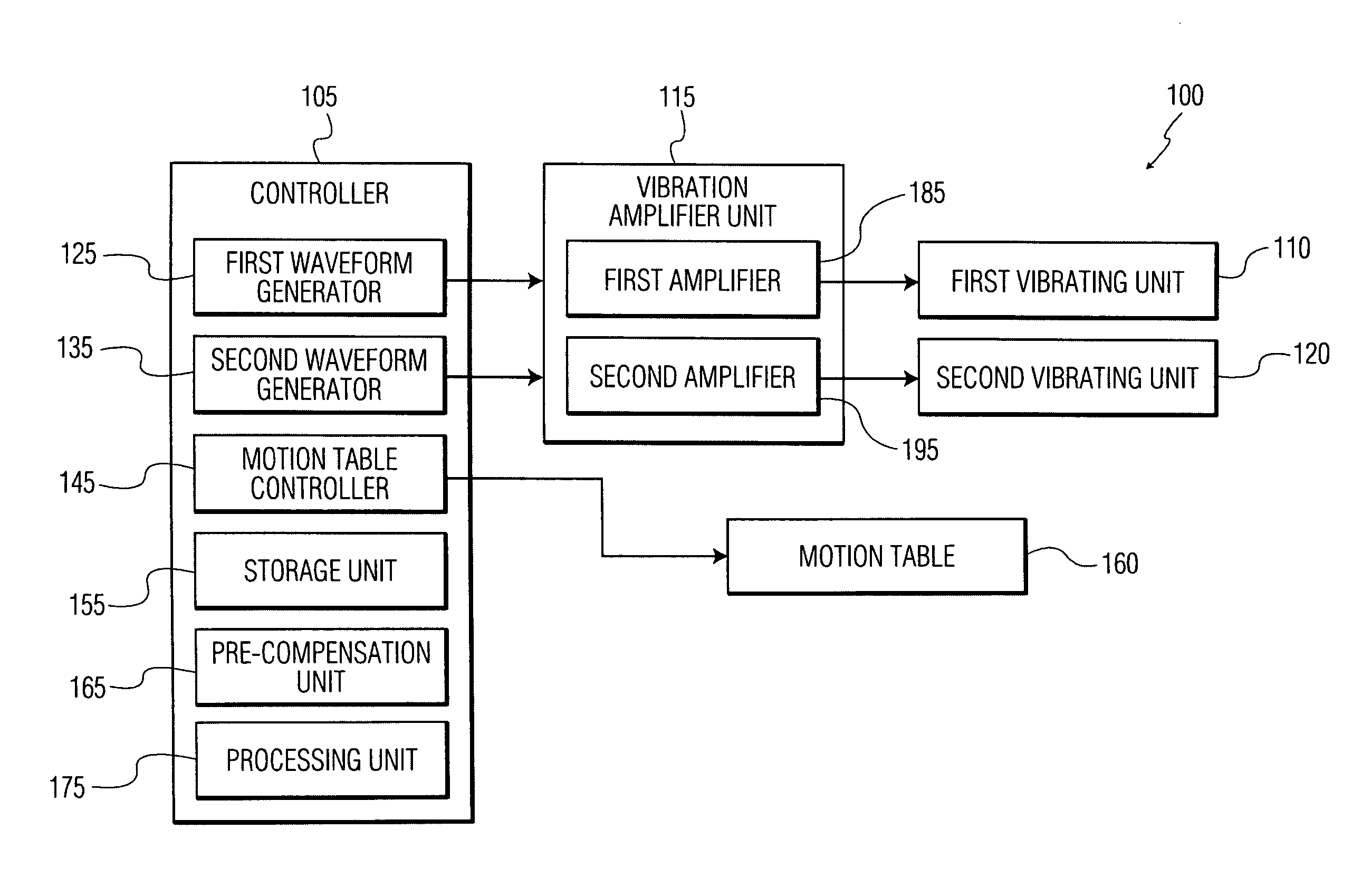
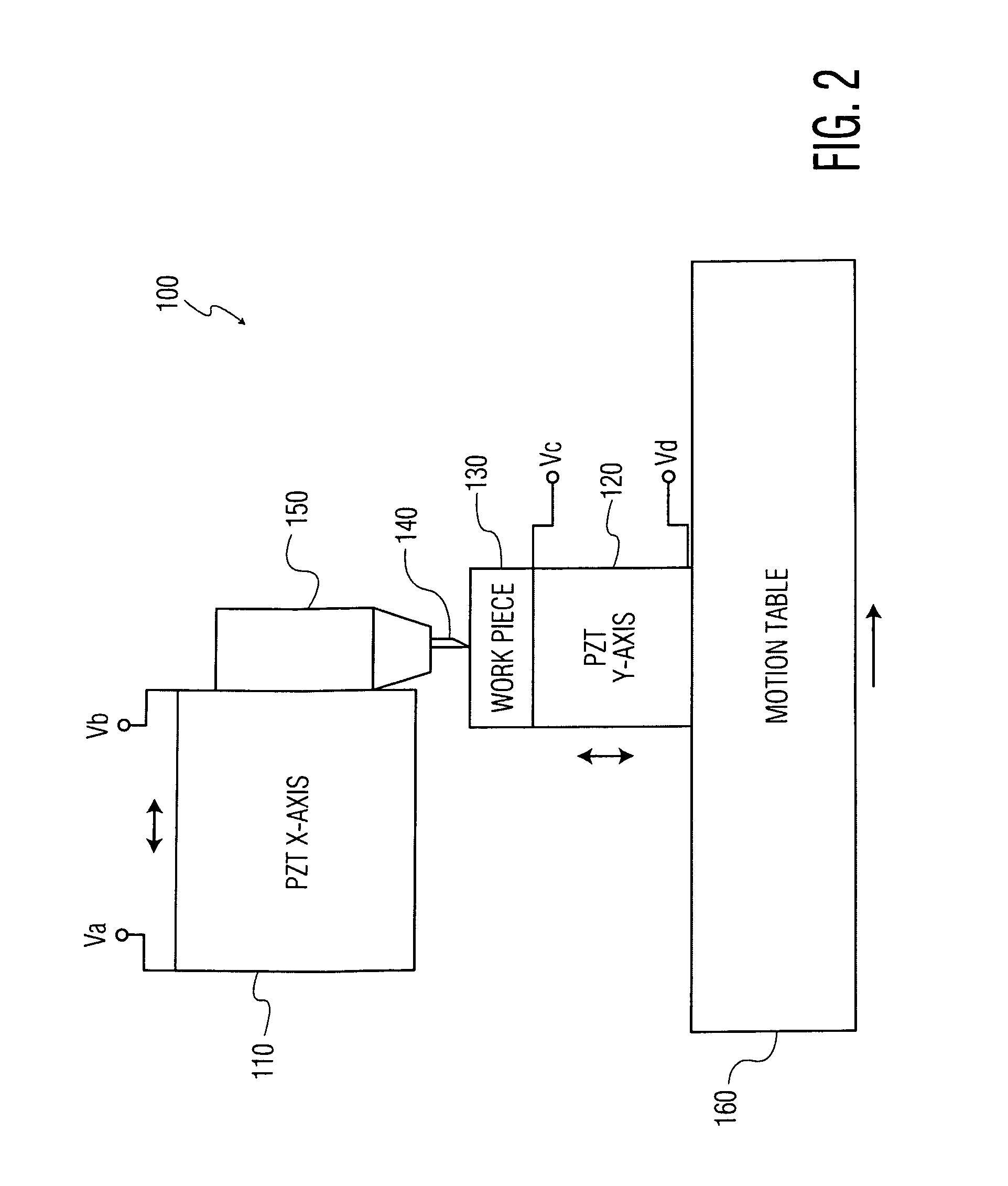
[0026] An exemplary embodiment of the present invention is a vibration machining apparatus with two independently coupled vibrating units. In this exemplary embodiment, an elliptical motion of a cutting tool relative to the workpiece may be realized by the use of two independent vibrating units. A number of different configurations of the two independent vibrating units may be possible because only relative elliptical motion is desired. That is, for example, the cutting tool may be vibrated along one axis, while the workpiece may be vibrated along a second, orthogonal or substantially orthogonal axis. Moreover, since the motion along each axis may be decoupled, the motion along each axis may be varied independently, allowing easily controlled variation of the elliptical motion.

[0027] By decoupling the motion of the cutting tool relative to the workpiece along the different axes, non-elliptical trajectories may also be realized. It may be advantageous to realize these non-elliptical...


PUM

PropertyMeasurementUnit
Angleaaaaaaaaaa
Angleaaaaaaaaaa
Angleaaaaaaaaaa

Abstract

A vibration machining apparatus and method of use. The vibration machining apparatus includes a cutting tool and a motion stage coupled to one of the cutting tool or the workpiece to move the cutting tool relative to the workpiece. A tangent to a machine path and a normal to the surface of the workpiece define a vibration plane. The vibration machining apparatus further includes a first vibrating unit coupled to one of the cutting tool or the workpiece to vibrate it along a first vibrational direction, substantially in the vibration plane, and a second vibrating unit coupled with one of the cutting tool or the workpiece to vibrate the one of the cutting tool or the workpiece coupled to the second vibrating unit along a second vibrational direction, different from the first direction and substantially in the vibration plane.

Description

FIELD OF THE INVENTION [0001] The invention relates to vibration machining, and, more particularly, to a method and apparatus for machining a work piece using two independently coupled vibrating units. BACKGROUND OF THE INVENTION [0002] Vibration assisted machining (VAM), has recently been developed. This machining method enables machining of material, such as for example, silicon carbide that previously could not be single point diamond turned due to excessive heating of the diamond tip. VAM systems, such as the Ultramill system developed at North Carolina State University, use two piezoelectric (PZT) actuators mounted sided by side to drive a diamond tool in an elliptic trajectory. The minor and major axes of the ellipse trajectory are determined by a T-shaped linkage geometry of the PZT actuators to the diamond used for machining. However, this linkage geometry does not allow for reduced tool lead-in and lead-out zones (i.e., transition zones) when entering or exiting a workpiece...

Claims


Application Information

Patent Timeline
IPC IPC(8): H01L41/00
CPCB23B29/125B23B2226/31B23B2260/108B24B13/046B23P25/00B24B1/04B23D5/00
Inventor LIU, XINBING
Owner PANASONIC CORP
Why Eureka
Try Eureka