Radar apparatus

a radar and apparatus technology, applied in the field of fmcw radar apparatus, can solve the problem of not being able to know from its processing, and achieve the effect of high accuracy, accurate and fast detection, and easy correction

Inactive Publication Date: 2007-03-08
FUJITSU GENERAL LTD
View PDF5 Cites 34 Cited by
  • Summary
  • Abstract
  • Description
  • Claims
  • Application Information

AI Technical Summary

Benefits of technology

[0018] As described above, according to the radar apparatus of the present invention, there is no need to provide special correction equipment, and besides, any changes which may exist or which have occurred in the characteristics of each receiver circuit system comprising a filter circuit and an AD converter for processing the received signal received by the antenna can be detected accurately and quickly even during normal operation, and a correction can be applied to the receiver circuit system in accordance with the result of the detection; accordingly, variations in received signal characteristics due to differences in processing performance between the receiver circuit systems can be easily corrected in an initial adjustment procedure performed at the factory before shipment, and furthermore, corrections can even be made as needed for temperature variations due to environmental changes during operation, thereby ensuring high accuracy at all times.
[0019] Furthermore, according to the radar apparatus of the present invention, if, initially, there exists a performance difference between the plurality of receiver circuit systems provided to correspond with the plurality of receiving antennas, or if the characteristics degrade due to aging of the receiver circuit systems, or a fault occurs in any one of the receiver circuit systems during the operation of the radar apparatus, corrections can be made in accordance with the change or difference in the characteristics due to the fault, etc.; in this way, the accuracy of the recognition operation of the radar apparatus can be maintained at a high level at all times.

Problems solved by technology

As the received signals are processed in this receiver circuit unit, there has been the problem that even when a change has occurred in the characteristics of the receiver circuit unit as described above, it is not possible to know from its processing result whether there is an error in the detection of the phase difference.

Method used


Image

  • Radar apparatus
  • Radar apparatus
  • Radar apparatus

Examples


Embodiment Construction

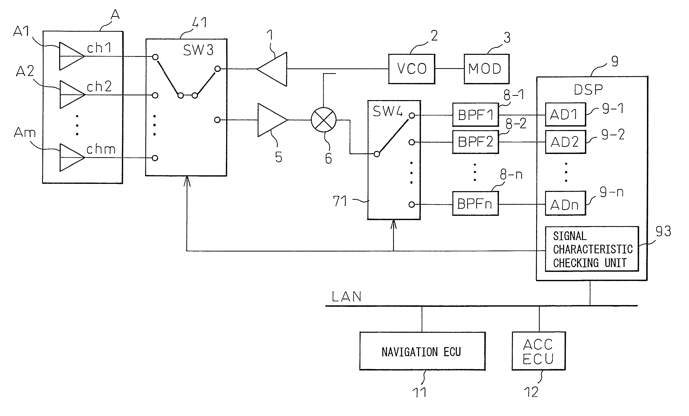
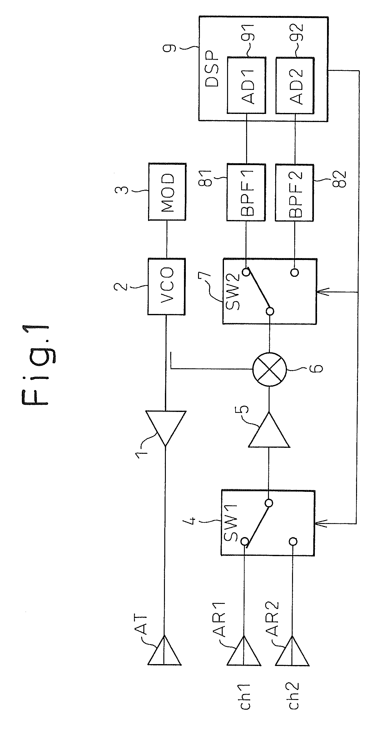
[0027] Next, embodiments of a radar apparatus according to the present invention will be described, but before proceeding to the description of the embodiments, an electronic scanning radar apparatus which performs digital beam forming (DBF), and which forms the basis of the radar apparatus of the present embodiment, will first be described in order to clarify the effect that the present invention offers.

[0028] An FM-CW radar apparatus transmits a continuous wave frequency-modulated, for example, in a triangular pattern toward a target such as a vehicle traveling ahead, and measures, for example, the distance to the vehicle ahead by receiving the transmitted wave returning back as a reflected wave. More specifically, the transmitted wave from the radar apparatus is reflected by the vehicle ahead, and the reflected wave is received as the received signal which is then mixed with the transmitted signal to produce a beat signal (radar signal). This beat signal is fast Fourier transfor...


PUM


Abstract

In an radar apparatus according to the present invention, any change detected in the characteristic of a receiver circuit is corrected during normal operation or at the time of an initial adjustment before shipment from factory and, furthermore, any change occurring in the characteristic due to aging or temperature variations in the operating environment is corrected as needed. In the radar apparatus which includes a plurality of receiver circuit systems to correspond with a plurality of receiving antennas, channel signals ch1 and ch2 having the same characteristics are generated by the switching operation of a second switch from a received channel signal received by an antenna selected by a first switch, and the thus generated signals are input to the respective receiver circuit systems. Any change in characteristic is detected by comparing signal level and phase between the channel signals converted from analog to digital. The characteristic of each receiver circuit system or the characteristic of each A-D converted output signal is corrected based on the result of the detection of each receiver circuit system.

Description

TECHNICAL FIELD [0001] The present invention relates to an FM-CW radar apparatus that uses a frequency-modulated (FM) continuous wave (CW) as a signal for transmission, and more particularly to an electronic scanning radar apparatus that is equipped with a plurality of antennas switchable to receive a transmitter signal returning back as a reflected wave, and that performs digital beam forming (DBF). DESCRIPTION OF THE RELATED ART [0002] A prior art DBF radar apparatus comprises a transmitter section which radiates a transmitter signal as an electromagnetic wave, and an array antenna having a plurality of antenna elements which receives, as a received signal, the electromagnetic wave reflected off an object. The antenna elements are each connected to one of a plurality of input terminals of a selector switch, and the plurality of input terminals are selectively connected one at a time to an output terminal of the selector switch. The incoming signal received by the selected antenna ...

Claims


Application Information

Patent Timeline
Patent Type & Authority Applications(United States)
IPC IPC(8): G01S7/40G01S7/02G01S13/34G01S13/93
CPCG01S7/4021G01S7/4056G01S13/34H03M1/12
Inventor SHIMA, NOBUKAZU
Owner FUJITSU GENERAL LTD
Why Eureka
Try Eureka