Image capturing apparatus and image capturing method

a technology image capturing method, which is applied in the field of image capturing apparatus, can solve the problems of inability to accurately detect back light state, and inability to use a camera using only the so-called contrast detection af system, etc., to achieve the effect of improving the resolution of photometry of objects, and increasing the number of divisions

Inactive Publication Date: 2007-03-08
SONY CORP
View PDF6 Cites 38 Cited by
  • Summary
  • Abstract
  • Description
  • Claims
  • Application Information

AI Technical Summary

Benefits of technology

[0009] This can be dealt with by increasing the number of division of the photometry device and improving the photometry resolution of the object. In particular, by using the output of the photometry device of a digital camera for photometry, the number of division can be further increased for photometry. However, if increasing the number of division, the amount of processing at the time of exposure determination also increases, so the general practice is to the photometry resolution not to detect the state of the object, but for use in improving the degree of freedom of shape of grouping together photometry regions.
[0010] It is therefore desirable in the present invention to provide an image capturing apparatus and image capturing method enabling the increase in the amount of processing at the time of exposure determination to be kept down and at the same time enabling effective use of the improved photometry resolution for back light detection.

Problems solved by technology

However, with the method disclosed in Japanese Patent Publication (B2) No. 7-27151, there was the disadvantage that when there was an object smaller than a photometry region or objects with a close luminance in a photometry region, the back light state could not be accurately detected.
However, it may be impossible to be used in a camera using only the so-called contrast detection AF system not using a focus detection image sensor, but detecting a change in contrast of an output image from an imager to detect the focus point.
Further, when another object with a close luminance was close to the side of the main object, sometimes the back light state failed to be detected.

Method used


Image

  • Image capturing apparatus and image capturing method
  • Image capturing apparatus and image capturing method
  • Image capturing apparatus and image capturing method

Examples


first embodiment

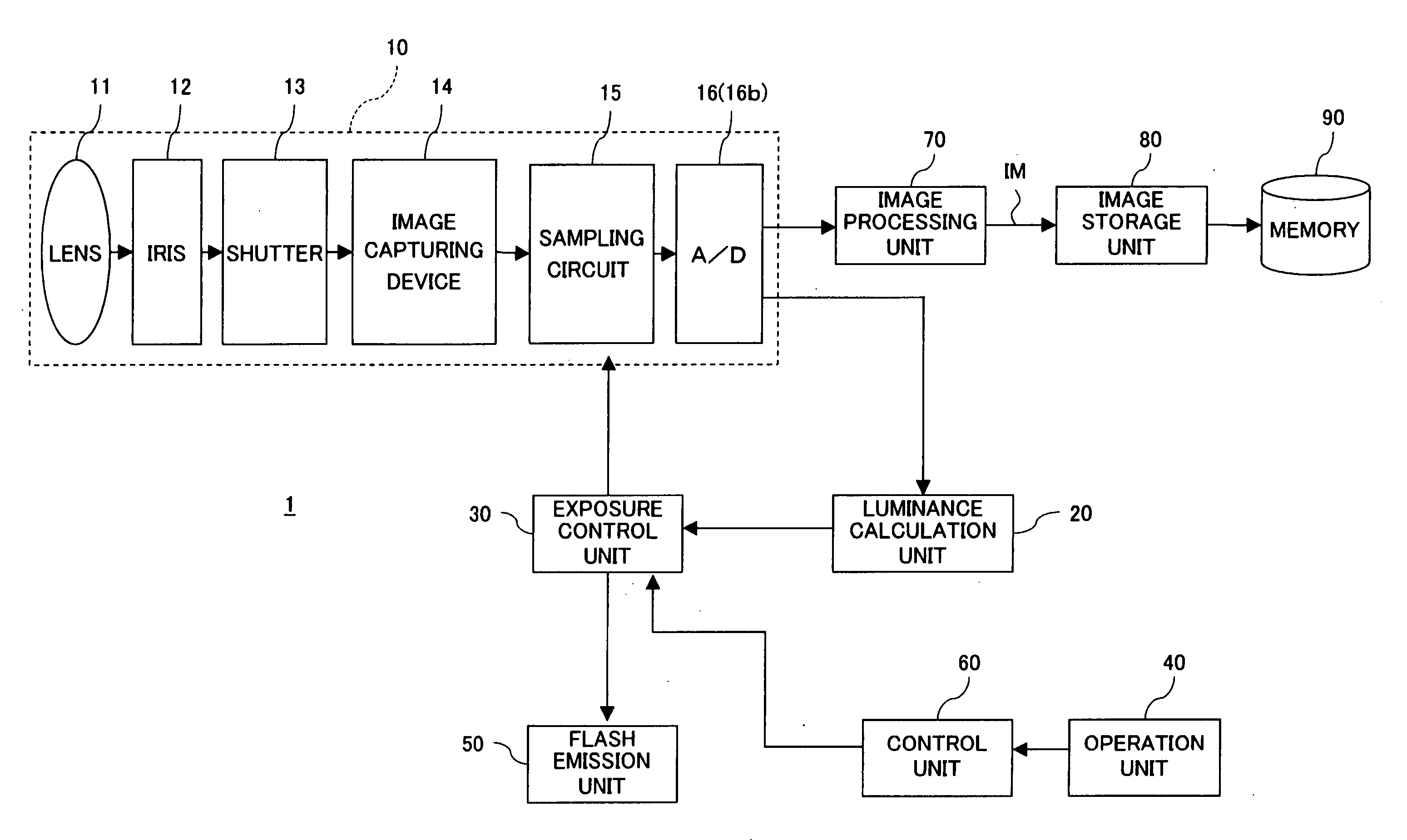
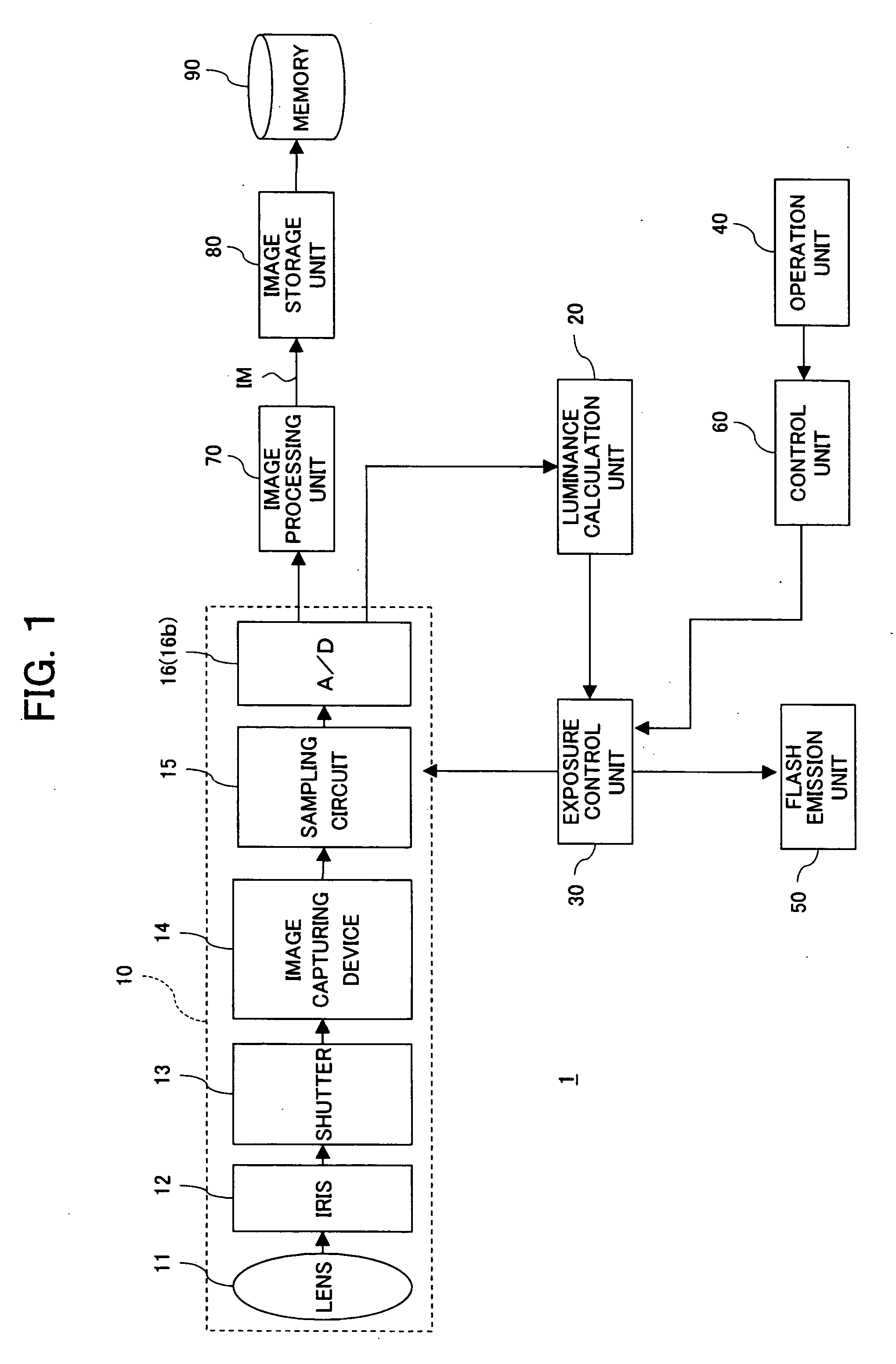
[0063]FIG. 1 is a view of the overall configuration of an image capturing apparatus according to the present invention.

[0064] The image capturing apparatus 1, as shown in FIG. 1, for example, has a camera module 10, luminance calculation unit 20, exposure control unit 30, operation unit 40, flash emission unit 50, control unit 60, image processing unit 70, image storage unit 80, and memory 90. Note that in this image capturing apparatus 1, the exposure control unit 30, control unit 60, and image processing unit 70 may be realized by electronic circuits or may be realized by a processor running a program.

[0065] Camera Module 10

[0066] The camera module 10 has, for example, a lens 11, iris 12, shutter 13, image capturing device 14, sampling circuit 15, and analog / digital (A / D) conversion circuit 16. The lens 11 receives light from the captured object and emits it to the iris 12. The iris 12 focuses the light received from the lens 11 and emits it to the shutter 13. The shutter 13 open...

second embodiment

[0124] Next, the image capturing apparatus of the present invention will be explained.

[0125]FIG. 18 is a view of the overall configuration of an image capturing apparatus according to the second embodiment of the present invention. The image capturing apparatus 1A according to the second embodiment differs from the image capturing apparatus 1 according to the first embodiment in the point of the processing of the exposure control unit 30A.

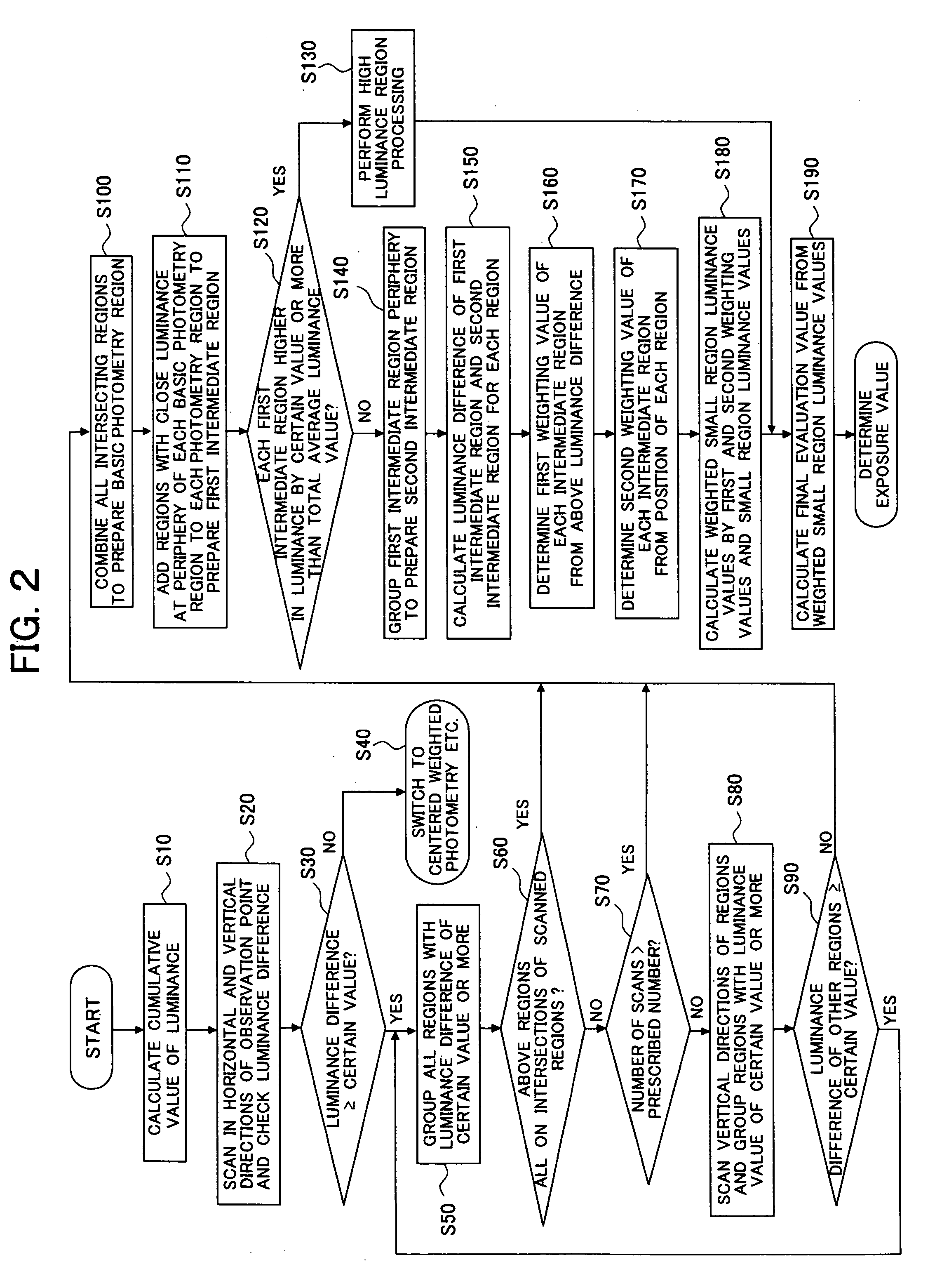
[0126] The exposure control unit 30A of the second embodiment, as will be explained in detail later, has a grouping function of producing a plurality of intermediate regions from the object luminances output from the luminance calculation unit 20, an evaluation value calculation function of producing exposure evaluation values from the intermediate region luminances, and a control function for image capture by a suitable exposure in accordance with the calculated luminances.

[0127] In this embodiment, the grouping function divides the object lumi...


PUM


Abstract

An image capturing apparatus keeping down an increase in the amount of processing at the time of exposure determination and at the same time enabling effective utilization of the improved photometry resolution for back light detection, having a luminance calculation unit dividing image data output from an image capturing device into a plurality of regions and measuring the luminance of each and an exposure control unit generating and grouping a plurality of intermediate regions from the object luminances output from the luminance calculation unit, generating an exposure evaluation value from the luminances of the intermediate regions, and suitably controlling the exposure for image capture in accordance with the measured luminances, and an image capturing method used for the same.

Description

CROSS REFERENCE TO RELATED APPLICATIONS [0001] The present invention contains subject matter related to Japanese Patent Applications No. 2005-257072 and No. 2005-257073 filed in the Japan Patent Office on Sep. 5, 2005, the entire contents of which being incorporated herein by reference. BACKGROUND OF THE INVENTION [0002] 1. Field of the Invention [0003] The present invention relates to an image capturing apparatus such as a digital camera and an image capturing method. [0004] 2. Description of the Related Art [0005] As technology for cameras etc., there is the so-called multi-segment photometry system which divides an object field into a lattice of a plurality of regions for photometry processing. For example, the art disclosed in Japanese Patent Publication (B2) No. 7-27151 calls for dividing a screen into 15 small regions, grouping together these into regions where the main object is present, intermediate regions grouping their peripheries, and other regions and using the luminanc...

Claims


Application Information

Patent Timeline
Patent Type & Authority Applications(United States)
IPC IPC(8): H04N5/238
CPCH04N5/2351H04N23/71H04N23/68H04N23/63H04N23/73H04N23/741
Inventor OKUNO, TAKAYUKI
Owner SONY CORP
Why Eureka
Try Eureka