Original scan line detection

Active Publication Date: 2007-03-08
LATTICE SEMICON CORP
View PDF79 Cites 1 Cited by
  • Summary
  • Abstract
  • Description
  • Claims
  • Application Information

AI Technical Summary

Benefits of technology

[0010] In certain embodiments, the comparison of calculated scan lines and scan lines in the frame can be facilitated by taking a magnitude of a difference b

Problems solved by technology

However, not all deinterlaced signals are of the same quality.
A problem is that once the interlaced signal is deinterlaced, the resulting progressive signal includes any inadequacies inherent in the

Method used


Image

  • Original scan line detection
  • Original scan line detection
  • Original scan line detection

Examples


Example

DETAILED DESCRIPTION OF THE DRAWINGS

[0028] In the following description, several specific details are presented to provide a thorough understanding of embodiments of the invention. One skilled in the relevant art will recognize, however, that the invention can be practiced without one or more of the specific details, or in combination with other components, etc. In other instances, well-known implementations or operations are not shown or described in detail to avoid obscuring aspects of various embodiments, of the invention.

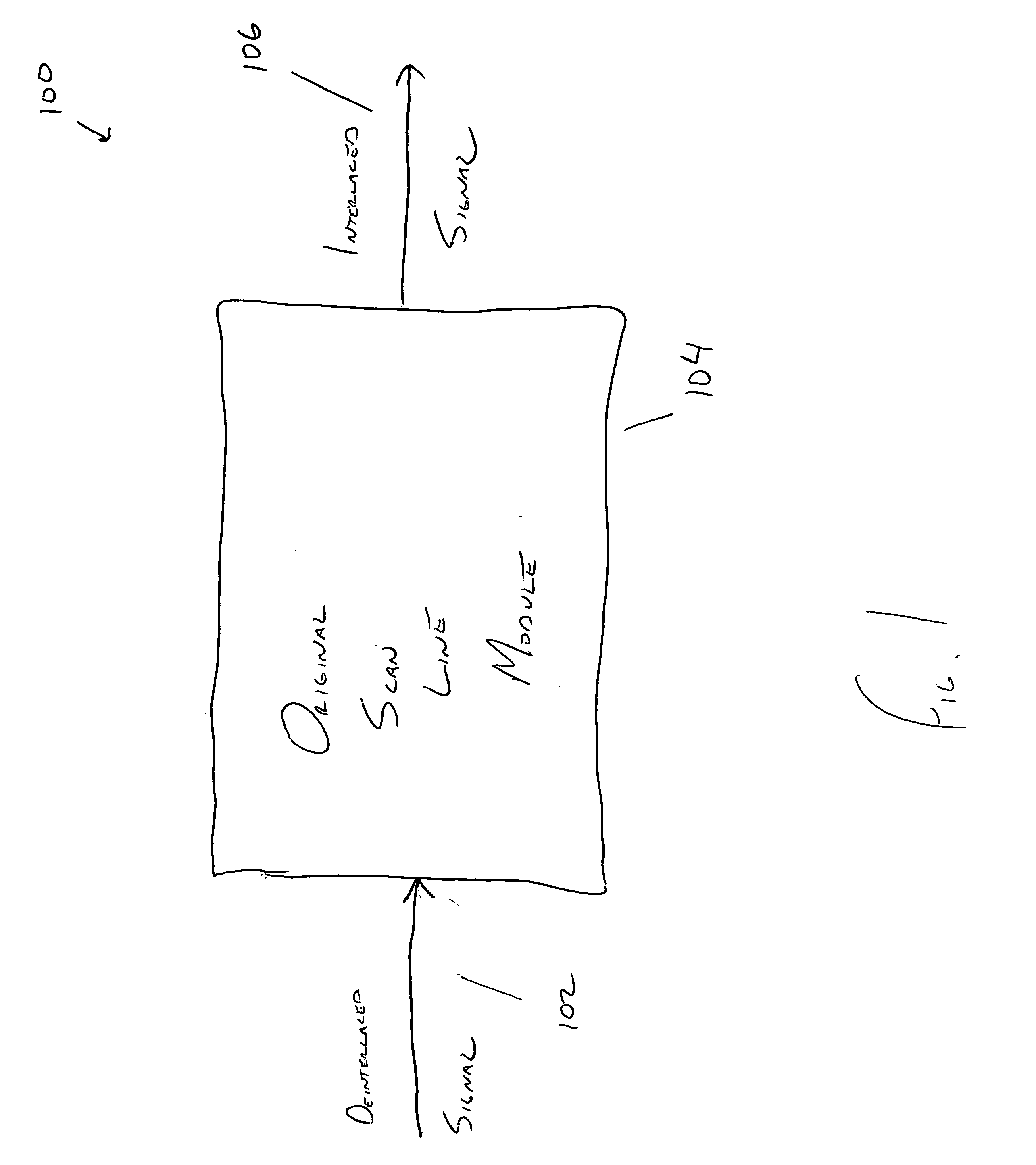
[0029]FIG. 1 depicts an example of a system 100 for interlacing a deinterlaced signal. In the example of FIG. 1, the system 100 includes an input 102, an original scan line module 104 and an output 106. As shown, the input 102 is a deinterlaced signal. The deinterlaced signal 102 is provided to the original scan line module 104. The original scan line module 104 detects original scan lines in the deinterlaced signal and generates an interlaced signal with orig...


PUM


Abstract

A technique for detecting original scan lines is disclosed. The technique involves receiving a deinterlaced signal with even scan lines and odd scan lines. After the deinterlaced signal is received, a determination is made as to whether the even scan lines or the odd scan lines are the original scan lines. In certain embodiments, an interlaced signal can be generated from the original scan lines. In other embodiments, an optimized deinterlaced signal can be generated using the original scan lines.

Description

CROSS-REFERENCE TO RELATED PATENTS AND PATENT APPLICATIONS [0001] The present application claims priority to and incorporates by reference the teaching of SOURCE-ADAPTIVE VIDEO DEINTERLACER provisional patent application No. 60 / 715,711, filed Sep. 8, 2005.BACKGROUND [0002] The conventional wisdom is that a progressive (i.e. deinterlaced) signal is superior to an interlaced signal. A progressive signal displays an entire frame while an interlace picture delivers two fields; one with even scan lines and one with odd scan lines. As such, a progressive signal displays a crisper, more brilliant picture without flicker. A progressive signal is also less susceptible to interlace or motion artifacts. [0003] There are a variety of techniques that may be implemented to deinterlace a signal. However, not all deinterlaced signals are of the same quality. Most deinterlacers employ vertical interpolation, weave or a motion adaptive technique to deinterlace an interlaced signal. Other advanced tec...

Claims


Application Information

Patent Timeline
IPC IPC(8): H04N7/01H04N11/20
CPCH04N7/012
Inventor ADAMS, DALE RICHARD
Owner LATTICE SEMICON CORP
Why Eureka
Try Eureka