360-° Image photographing apparatus

Inactive Publication Date: 2007-03-08
HITACHI LTD
View PDF7 Cites 40 Cited by
  • Summary
  • Abstract
  • Description
  • Claims
  • Application Information

AI Technical Summary

Benefits of technology

[0012] From the explanation given so far, an object of the present invention is to acquire the images of an actually-existing object which is seen from directions of 360°. Simultaneously, this acquisition is made executable without performing troublesome tasks in the image processing such as set up of the photographing target and set up of cameras.

Problems solved by technology

In this technology, however, the resultant image displayed is not a one acquired by photographing the target object, i.e., an actually-existing object.
This results in a lack of reliability.
In this technology, however, the apparatus itself is the considerably large-scaled one.
This makes it difficult to acquire the image which results from looking up at the target object from below.
In this technology, however, the marker positions are fixed, and no consideration is given to changing the posture of the target object either.
This causes a problem to occur which is basically the same as the one in JP-A-2004-264492.
Namely, in the above-described conventional technologies, it is difficult to acquire the photographing-target image which results from looking at the target object from directions of 360° including the up-and-down direction.

Method used


Image

  • 360-° Image photographing apparatus
  • 360-° Image photographing apparatus
  • 360-° Image photographing apparatus

Examples


Embodiment Construction

[0023] Hereinafter, referring to the drawings, the explanation will be given below concerning an embodiment of the present invention.

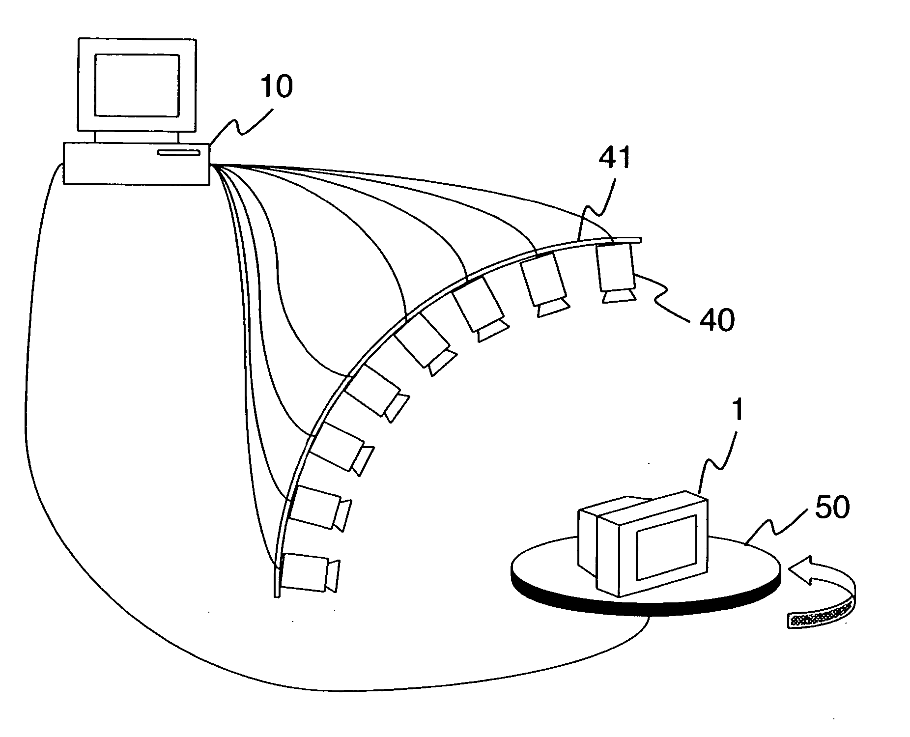
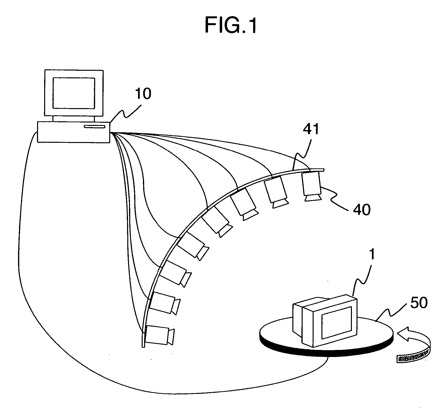
[0024]FIG. 1 is a diagram for illustrating the system configuration of the present embodiment.

[0025] The present system includes a computer 10, a photographing target 1, a turn table 50 which is rotated on each set-angle basis, a plurality of photographing devices 40 for acquiring multi-viewpoint images with the photographing at one time, and an arc-shaped photographing-device set-up table 41 set up along a circle perpendicular to the turn table 50. The computer 10 is connected to each of the plurality of photographing devices 40 and the turn table 50.

[0026] In the present system, at first, the photographing target 1 is set up on the turn table 50, then fixing the respective photographing devices 40 to the photographing-device set-up table 41 with an equal spacing set therebetween. The respective photographing devices 40 photograph the photographing...


PUM


Abstract

A computer includes a photographing unit for photographing every time a turn table is rotated and acquiring images of the photographing target from a plurality of photographing devices; a coordinate-system setting unit for setting a coordinate system; position of an extracted feature point of the photographing target being defined as reference of the coordinate system; a viewpoint-parameter calculation unit for calculating viewpoint parameters on the basis of the coordinate system set by the coordinate-system setting unit and camera parameters such as focal lengths of the photographing devices, the viewpoint parameters including position data of the photographing devices and direction data of the photographing devices are oriented; and a correspondence-data storage unit for storing the images and the viewpoint parameters being made correlated with each other, the images being acquired by the photographing unit, the viewpoint parameters being calculated by the viewpoint-parameter calculation unit.

Description

INCORPORATION BY REFERENCE [0001] The present application claims priority from Japanese application JP2005-255825 filed on Sep. 5, 2005, the content of which is hereby incorporated by reference into this application. BACKGROUND OF THE INVENTION [0002] 1. Field of the Invention [0003] The present invention relates to multi-viewpoint image photographing which uses a plurality of cameras. [0004] 2. Description of the Related Art [0005] As a technology for displaying a certain target object on a screen in such a manner that this target object can be seen from arbitrary directions, there exists a one which applies CG (Computer Graphics) such as Image Based Rendering. [0006] Also, as a technology for displaying on a screen a target object photographed by a camera, there exists a one relating to the following photographing apparatus (; refer to JP-A-2004-264492): By locating a plurality of cameras within a three-dimensional space, the photographing apparatus makes it possible to photograph...

Claims


Application Information

Patent Timeline
IPC IPC(8): G03B35/00G03B41/00G06T1/00G06T3/00G06T19/00H04N5/225H04N13/02
CPCG03D9/02
Inventor BENIYAMA, FUMIKOMORIYA, TOSHIO
Owner HITACHI LTD
Why Eureka
Try Eureka