
Process cartridge and an image forming apparatus having the same

a technology of process cartridges and forming apparatuses, applied in electrographic process apparatus, instruments, optics, etc., can solve the problems of ineffective use of cartridges, many significant deficiencies in printed images, and sensitive toner supply to the photoconductive body for developing latent electrostatic images, etc., to achieve the effect of completely and readily separating a developing nip

Active Publication Date: 2007-03-08
HEWLETT PACKARD DEV CO LP
View PDF4 Cites 25 Cited by
  • Summary
  • Abstract
  • Description
  • Claims
  • Application Information

AI Technical Summary

Benefits of technology

[0012] Accordingly, aspects of the present invention have been developed in order to solve the above and / or other problems associated with the related art. An aspect of the present invention is to provide a process cartridge which is capable of separating a developing nip completely and readily without having an adverse effect on a developing roller or other related parts.
[0013] Another aspect of the present invention is to provide an image forming apparatus which is capable of automatically maintaining or separating the developing nip when the process cartridge is installed into or removed from a main body frame, respectively.

Problems solved by technology

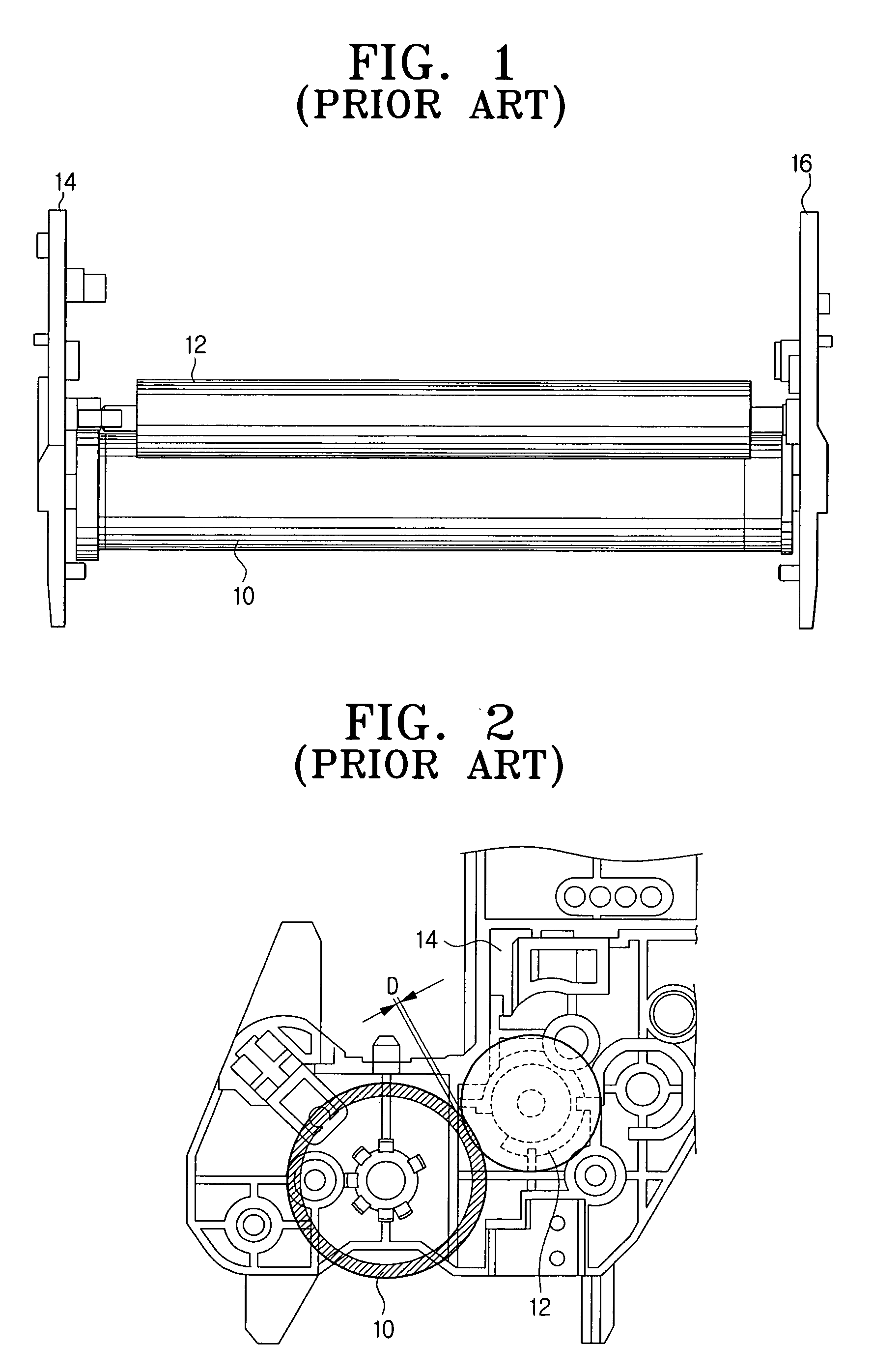
However, in the contact development method, the amount of a toner supplied to the photoconductive body for developing the latent electrostatic image is very sensitive to the size of the developing nip D (see FIG. 2), i.e., an amount of contact surface between the photoconductive body and the developing roller.
If the developing nip is outside of this range, there will be many significant deficiencies in the printed image.
In practice, the conventional process cartridge has a specific developing nip fixed at the time of manufacture before it is initially put into circulation in the market; however the cartridge may not actually be used by a user until after a long period of time.
Therefore, since the process cartridge may be in circulation for some time while the developing roller and the photoconductive body are in pressure contact with each other due to the initially set developing nip, several problems may arise, for instance the developing roller may be deformed by the pressure from the photoconductive body or the toner in the developing nip D may adhere to either the photoconductive body, the developing roller or both.
But, problems with these techniques, such as white voids appearing in both side portions of an image, remain unresolved.
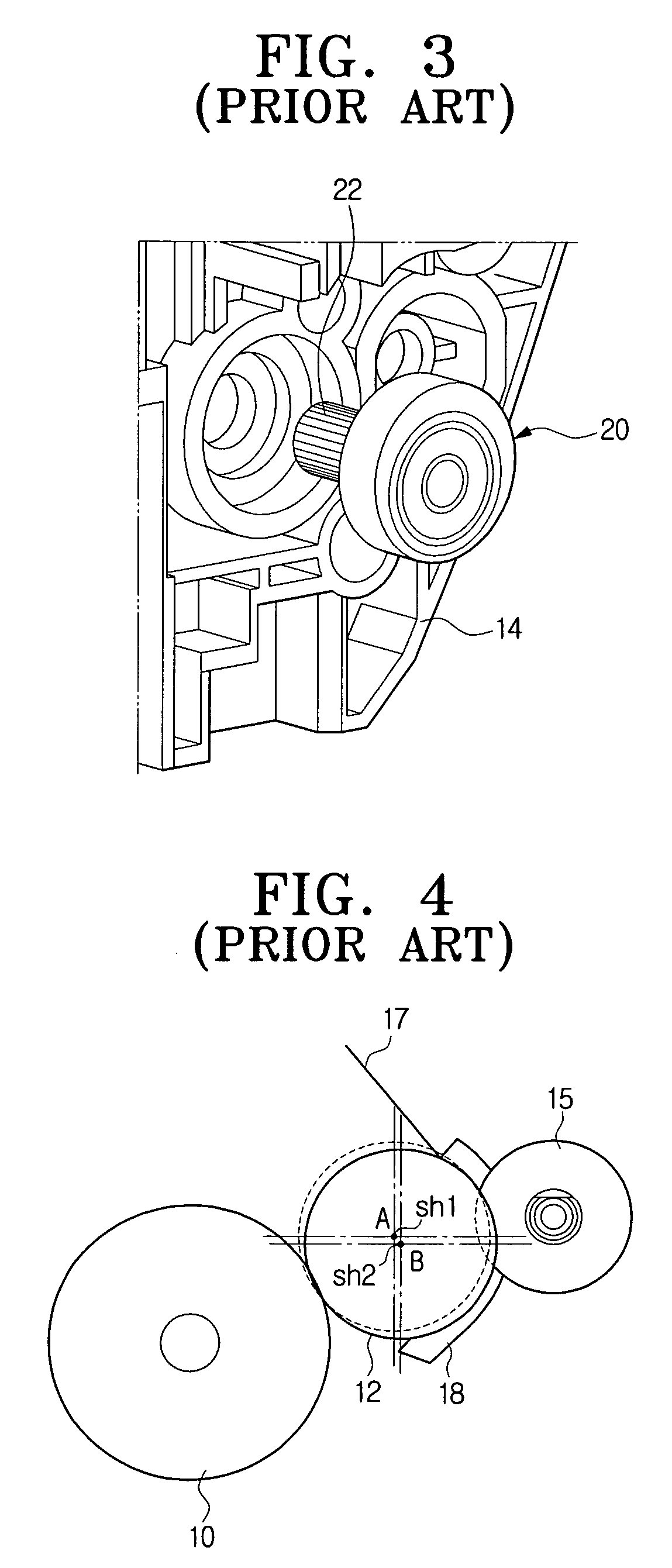
However, a drawback in the aforementioned technology, is that since the eccentric cam 20 moves the center axis of the developing roller 12 from a point sh1 to a point sh2 as shown in FIG. 4, thus moving the developing roller 12 directly, a supply roller 15 and a blade 17 adjacent to the developing roller 12 are also affected.
In addition, this may have an adverse effect on various gears coupled to the developing roller, the supply roller and the like, i.e., a gear train needed to drive the rotation of these cartridge components.

Method used


Image

  • Process cartridge and an image forming apparatus having the same
  • Process cartridge and an image forming apparatus having the same
  • Process cartridge and an image forming apparatus having the same

Examples


Embodiment Construction

[0035] Reference will now be made in detail to the present embodiments of the present invention, examples of which are illustrated in the accompanying drawings, wherein like reference numerals refer to the like elements throughout. The embodiments are described below in order to explain the present invention by referring to the figures.

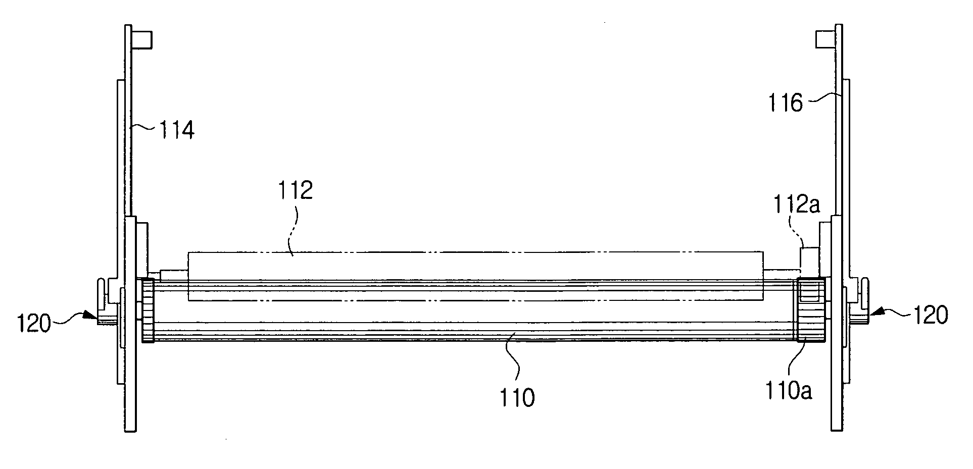
[0036]FIG. 5 is a perspective view of a process cartridge in accordance with an embodiment of the present invention, and FIG. 6 is a front view illustrating an internal configuration of important parts of the process cartridge.

[0037] Referring to the drawings, a process cartridge 100 of the present invention includes side plates 114, 116, a developing roller 112, a photoconductive body 110 and a center shifting member 120.

[0038] The side plates 114 and 116 form an outer appearance of the process cartridge 100, and support both end portions of the developing roller 112 and the photoconductive body 110 such that the developing roller 112 and the phot...


PUM


Abstract

A process cartridge and an image forming apparatus including the same, the process cartridge comprising a side plate; a developing roller rotatably supported at the side plate; a photoconductive body having a center axle rotatably supported at the side plate so as to be located adjacent to the developing roller; and a center shifting member for moving the center axle of the photoconductive body from a first position to a second position so as to separate a developing nip between the photoconductive body and the developing roller. The image forming apparatus includes the process cartridge, so that it can establish and maintain the developing nip between the photoconductive body and the developing roller to print an image or separate the developing nip to circulate the process cartridge in the market.

Description

CROSS-REFERENCE TO RELATED APPLICATION [0001] This application claims the benefit of Korean Application No. 2005-83798, filed Sep. 8, 2005, in the Korean Intellectual Property Office, the disclosure of which is incorporated herein by reference. BACKGROUND OF THE INVENTION [0002] 1. Field of the Invention [0003] Aspects of the present invention relate to an image forming apparatus. More particularly, the present invention relates to a process cartridge capable of readily rendering a developing nip that is otherwise separated during shipping, distribution, and storage while circulated in the market, and an image forming apparatus having the same. [0004] 2. Description of the Related Art [0005] In a conventional image forming apparatus which adopts an electrophotographic process, such as a laser printer, a copying machine or a facsimile, a process cartridge is used to combine a photoconductive body and a processing means into one cartridge capable of being installed into and removed fr...

Claims


Application Information

Patent Timeline
Patent Type & Authority Applications(United States)
IPC IPC(8): G03G21/18G03G15/00G03G15/08
CPCG03G21/1821G03G2221/1807G03G2221/1654G03G2221/1609G03G15/06
Inventor KWEON, DAE-SEOB
Owner HEWLETT PACKARD DEV CO LP
Learn More