Holder for flat flexible circuitry

a flexible circuit and holder technology, applied in the direction of electrical apparatus, connection, coupling device connection, etc., can solve the problems of low rigidity, deformation or inadequate insertion of the ffc, and often encountered in connecting so as to facilitate interconnection or terminating the ffc

Inactive Publication Date: 2007-03-08
MOLEX INC
View PDF13 Cites 37 Cited by
  • Summary
  • Abstract
  • Description
  • Claims
  • Application Information

AI Technical Summary

Benefits of technology

[0005] An object, therefore, of the invention is to provide a new and improved holder for an FFC to facilitate interconnecting or terminating the FFC.

Problems solved by technology

Problems often are encountered in connecting or terminating an FFC because of its low rigidity.
If a bare FFC is inserted into a mating connector, insertion resistance often causes deformation or inadequate insertion of the FFC.
Unfortunately, such ZIF connectors are unduly complex and excessively large in size.
In other words, a greater portion of the FFC (i.e., between its side edges) is not supported by the lock member and therefore remains flexible and unstable.
If a thick metallic reinforcement sheet of sufficient strength is used, the weight increases significantly with resulting difficulty in handling, and there is a significant cost increase.

Method used


Image

  • Holder for flat flexible circuitry
  • Holder for flat flexible circuitry
  • Holder for flat flexible circuitry

Examples


Embodiment Construction

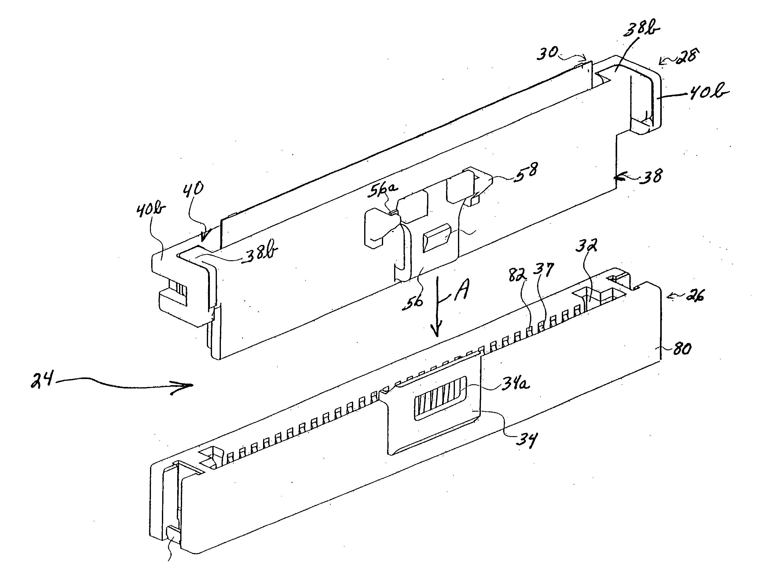
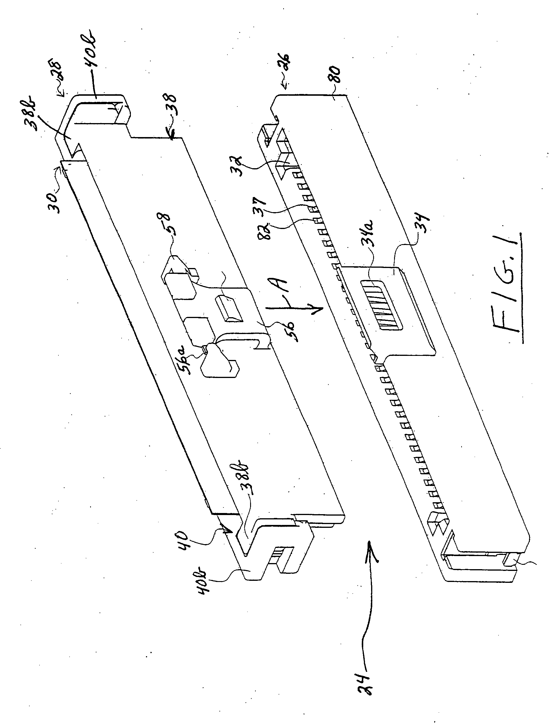
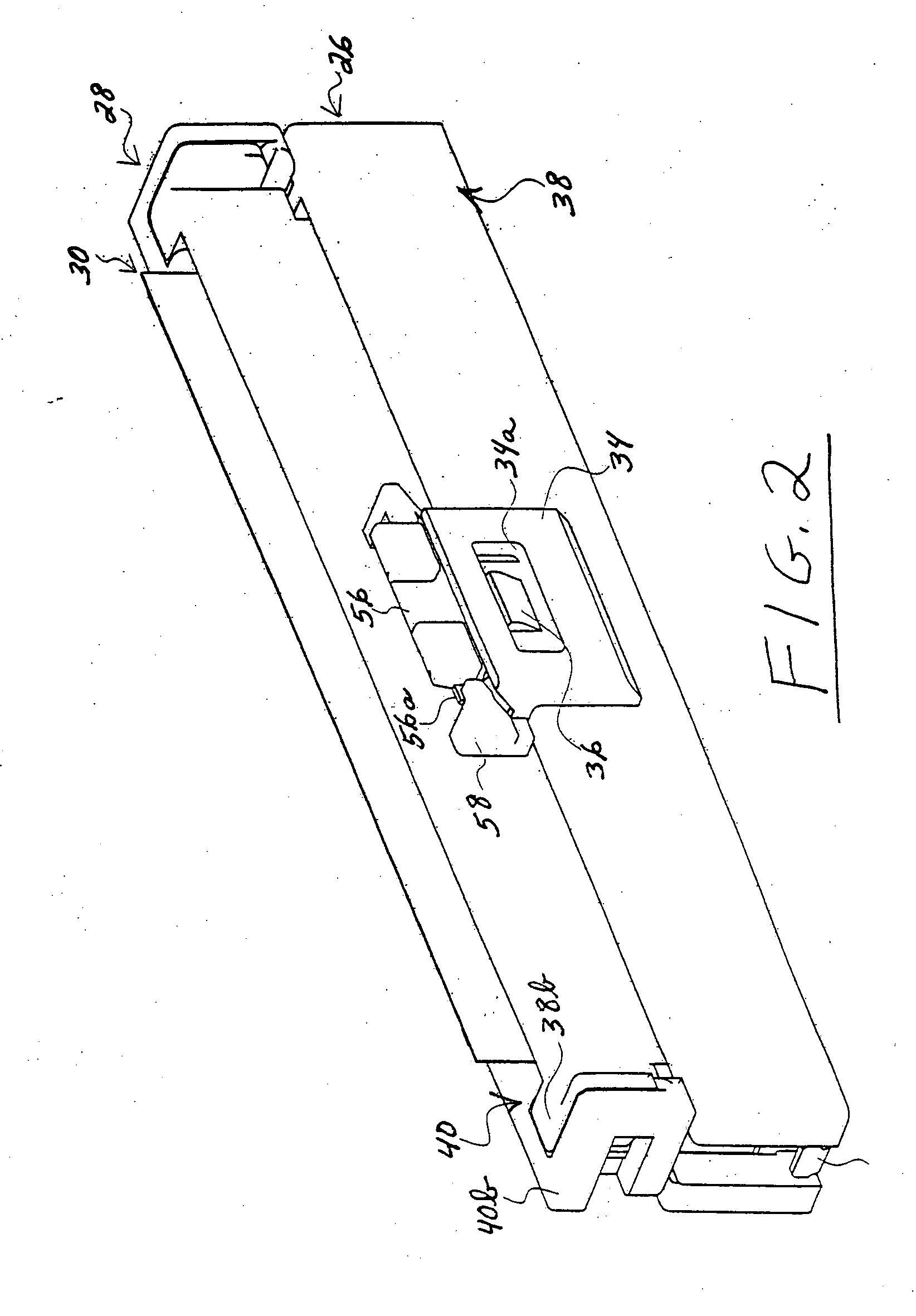
[0030] Referring to the drawings in greater detail, and first to FIGS. 1 and 2, the invention is embodied in an electrical connector assembly, generally designated 24, which includes a first embodiment of a connector, generally designated 26, for receiving a cable holder, generally designated 28, which is attached to a distal end portion of a flat flexible cable (“FFC”), generally designated 30. After the FFC is attached to the holder, the holder and FFC are inserted into a receptacle 32 in the connector in the direction of arrow “A” (FIG. 1). The connector has a latch 34 with a latch aperture 34a for receiving a chamfered latch boss 36 on the holder to latch the holder to the connector as seen in FIG. 2. When the holder and FFC are fully inserted into the connector, exposed conductors (described hereinafter) on the FFC will engage terminals 37 (FIG. 1) exposed within receptacle 32 of connector 26.

[0031] Referring to FIGS. 3, 5 and 6 in conjunction with FIGS. 1 and 2, cable holder ...


PUM


Abstract

The disclosure describes a holder for attachment to a distal end portion of a flat flexible cable (FFC) and directly engaging exposed conductors of the FFC with appropriate terminals of a mating connector. The FFC has opposite side edges and opposite flat surfaces between the side edges. The holder includes a pair of interengaging gripping members for gripping the opposite flat surfaces of the FFC between the opposite side edges thereof. A latch is provided on at least one of the gripping members for latching the holder to the mating connector, with the exposed conductors of the FFC in direct engagement with the terminals of the mating connector.

Description

FIELD OF THE INVENTION [0001] This invention generally relates to the art of electrical connectors and, particularly, to a holder for interconnecting or terminating flat flexible circuitry. BACKGROUND OF THE INVENTION [0002] A flat flexible circuit or cable conventionally includes an elongated flat flexible dielectric substrate having laterally spaced strips of conductors on one or both sides thereof. The conductors often are covered with a thin, flexible protective layer on one or both sides of the circuit. If protective layers are used, the layers are stripped or cutouts are formed therein to expose the underlying conductors where the conductors are to engage the conductors or terminals of a complementary mating connecting device which may be a second flat flexible circuit, a printed circuit board or the terminals of a mating connector. The flat flexible circuit may be a flat flexible cable, a flexible printed circuit board or the like. Hereinafter, such circuitry will be referred...

Claims


Application Information

Patent Timeline
Patent Type & Authority Applications(United States)
IPC IPC(8): H01R12/24
CPCH01R12/57H01R13/6272H01R13/506H01R12/79
Inventor HIRATA, TOSHIHISA
Owner MOLEX INC
Why Eureka
Try Eureka