Control method of device in storage system for virtualization

a control method and storage system technology, applied in the field of storage device systems, can solve the problems of affecting data copy processing, requiring replacement of devices constituting the computer system, and reducing output, so as to achieve the effect of reducing input/output processing capacity

Inactive Publication Date: 2007-03-08
HITACHI LTD
View PDF13 Cites 64 Cited by
  • Summary
  • Abstract
  • Description
  • Claims
  • Application Information

AI Technical Summary

Benefits of technology

[0011] In order to achieve the equalization / optimization of the input / output workload between the storage systems, the present invention provides the following means for device transfer between the storage systems controlling the virtualization of the devices (hereafter referred to as a “virtualization control storage system”).
[0011] In order to achieve the equalization / optimization of the input / output workload between the storage systems, the present invention provides the following means for device transfer between the storage systems controlling the virtualization of the devices (hereafter referred to as a “virtualization control storage system”).

Problems solved by technology

However, as described above, when a large amount of data is stored for a long time, i.e., several decades during the life span of the storage, the devices constituting the computer system are needed to be replaced in the middle of the data storage period.
However, when the conventional input / output processing of the device performed by the first storage system, the data copy processing may be adversely affected, for example, a decrease in output.
Furthermore, the large amount of device data that will be migrated needs to be copied in its entirety, consequently, a large amount of time is necessary for the device transfers between the first storages.

Method used


Image

  • Control method of device in storage system for virtualization
  • Control method of device in storage system for virtualization
  • Control method of device in storage system for virtualization

Examples


first embodiment

[0042] The first embodiment is described below with reference to FIGS. 1 through 10.

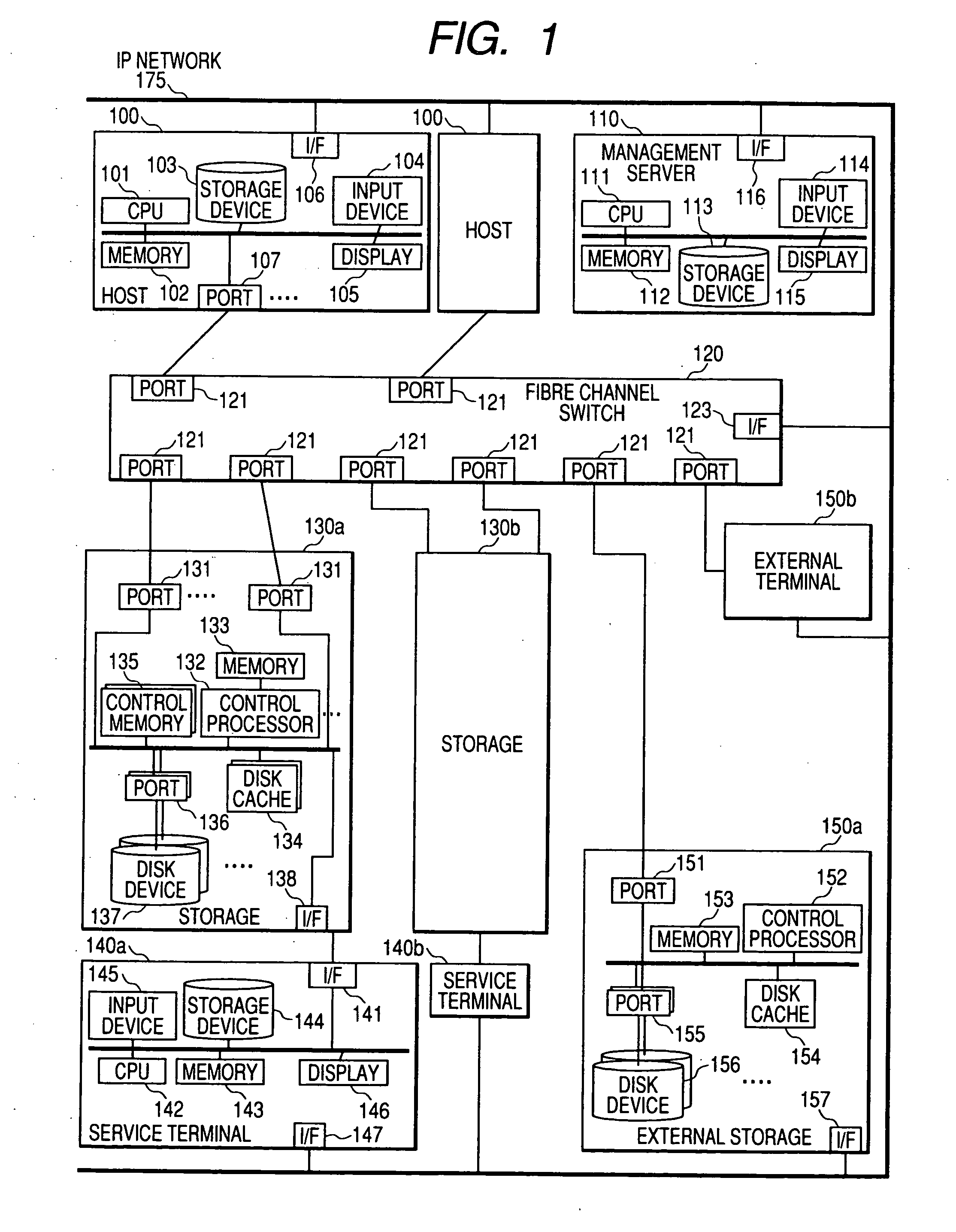
[0043]FIG. 1 shows an example of a hardware configuration of a computer system in accordance with the first embodiment of the present invention.

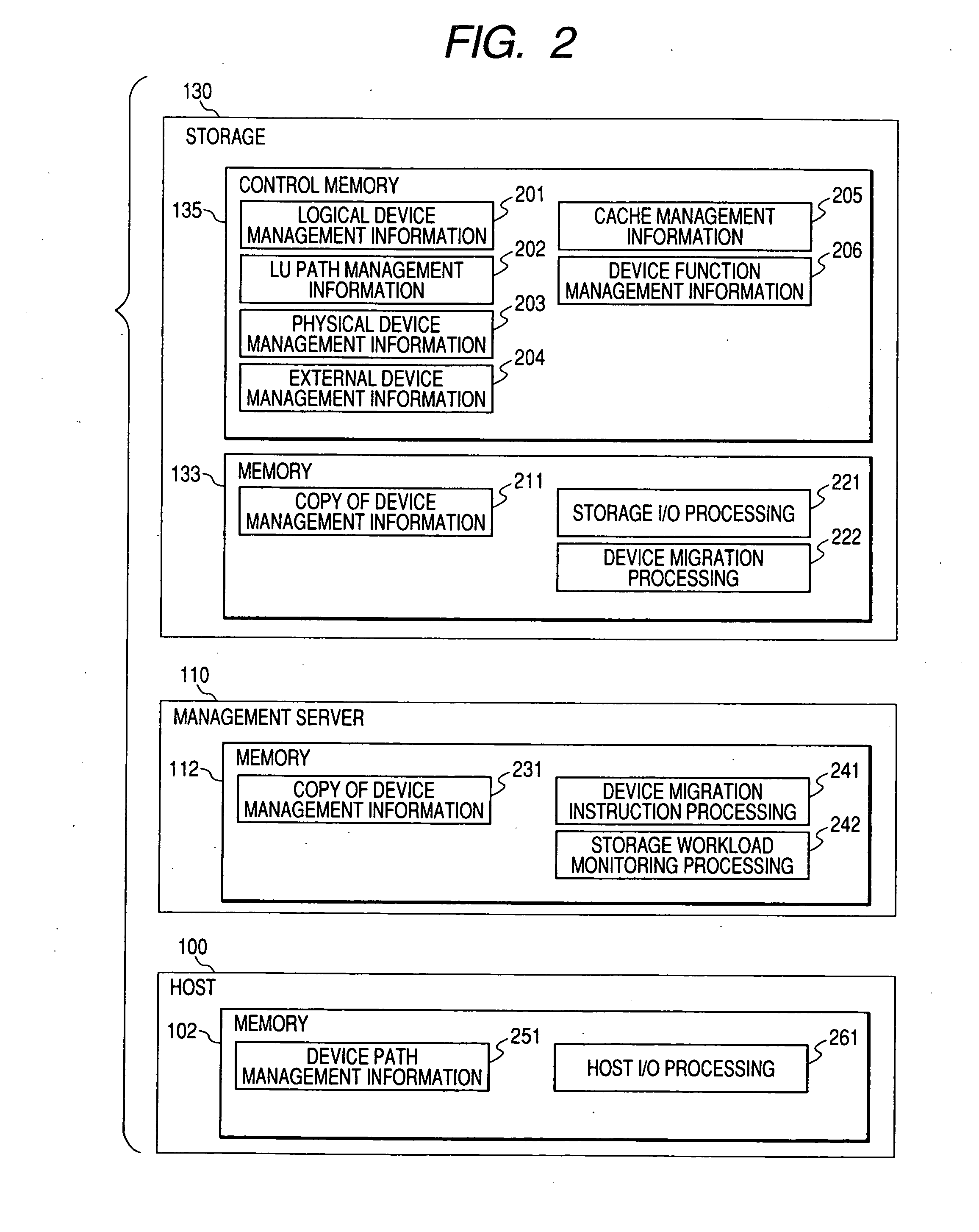
[0044] The computer system includes at least one host 100, a management server 110, a fibre channel switch 120, storage systems 130a and 130b (generally referred to as a “storage system 130”), service terminals 140a and 140b (generally referred to as a “service terminal 140”), and external storages 150a and 150b (generally referred to as an “external storage 150”). The host 100, the storage system 130 and the external storage 150 are connected to ports 121 of the fibre channel switch 120 through ports 107, 131 and 151, respectively. Also, the host 100, the storage system 130, the external storage 150 and the fibre channel switch 120 are connected to the management server 110 from interface control sections 106, 138, 157 and 123, respectively, through an IP ...

second embodiment

[0142] The second embodiment is described with reference to FIGS. 1 through 6, 10, and 12 through 14. Since the first and second embodiments share many common features, only differences between them will be described.

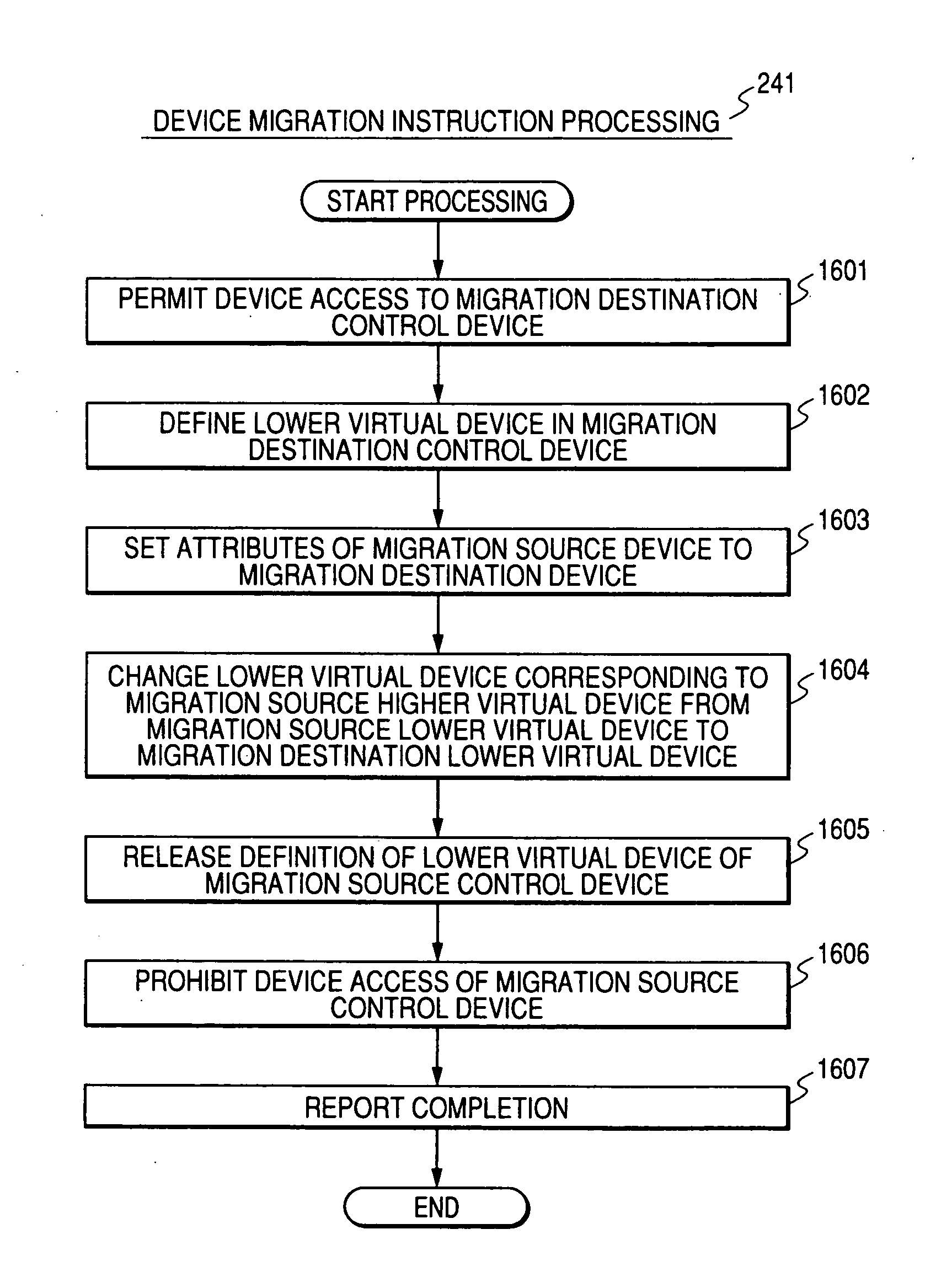
[0143] In the second embodiment, first, in the destination storage system 130b, an external device defines that virtualizes a first logical device of a migration source storage system 130a and a second logical device defines corresponding to the external device, so that access target of one or more hosts 100 are switched to the second logical device. Then, after dirty update data which has congested in the disk cache 134 of the migration source storage system 130a is written into the third logical device of the external storage 150, a separate external device virtualizing the third logical device in the migration destination storage system 130b defines, and correlation between the second logical device and the latter external device are switched so that the second logi...


PUM


Abstract

In a system where a first storage system and a second storage system are connected to a third storage system, when the first storage system virtualizes and provides a device in the third storage system as a device in its own storage system, update data stored in a cache in the first storage system is written into the device of the third storage system to be reflected, attributes of the device are transferred to the second storage system, and the second storage system virtualizes the device of the third storage system as a device of its own storage system.

Description

CROSS REFERENCE TO RELATED APPLICATIONS [0001] This application relates to and claims priority from Japanese Patent Application No. 2005-255826, filed on Sep. 5, 2005, the entire disclosure of which is incorporated herein by reference. BACKGROUND OF THE INVENTION [0002] 1. Field of the Invention [0003] The present invention relates to a storage device system (hereafter referred to as a “storage system”) for storing data used by a computer in a computer system. More specifically, the present invention relates to a control method of a storage system by which a host computer (hereafter referred to as a “host”) is connected to one or more other storage systems, and the storage areas in the other storage systems (“hereafter referred to as a “device”) are virtualized as a device of its own. [0004] 2. Description of the Related Art [0005] The amount of data received / transmitted by computers has remarkably increased as information systems are rapidly developing, for example, expansion of th...

Claims


Application Information

Patent Timeline
Patent Type & Authority Applications(United States)
IPC IPC(8): G06F13/00G06F12/00
CPCG06F3/0613G06F3/0617G06F3/067G06F3/0647G06F3/0635
Inventor YAMAMOTO, YASUTOMOHONMA, HISAOSATOYAMA, AI
Owner HITACHI LTD
Why Eureka
Try Eureka