Eureka AIR delivers breakthrough ideas for toughest innovation challenges, trusted by R&D personnel around the world.

Angle adjusting device for blind slats

Inactive Publication Date: 2007-03-15
NIEN MADE ENTERPRISE CO LTD
View PDF6 Cites 20 Cited by
  • Summary
  • Abstract
  • Description
  • Claims
  • Application Information

AI Technical Summary

Benefits of technology

[0006] The feature of the invention is a base fixed in an upper elongate case of a blind, a winding shaft pivotally connected with the base and rotated by a rotation control member to rotate clockwise or counterclockwise, and a string wound on the winding shaft and having two ends extending out of a first end side of the base and connected with two hanging ropes of a support rope for blind slats. Then the angle-adjusting device can be handled for adjusting the angle of the blind slats with ease.

Problems solved by technology

However, the conventional angle adjusting device has many components, such as the base, the winding shaft, the rotating shaft, the plural shaft bases and the plural fixing members, complicating its structure and subsequently heighten its cost.

Method used


Image

  • Angle adjusting device for blind slats
  • Angle adjusting device for blind slats
  • Angle adjusting device for blind slats

Examples


Embodiment Construction

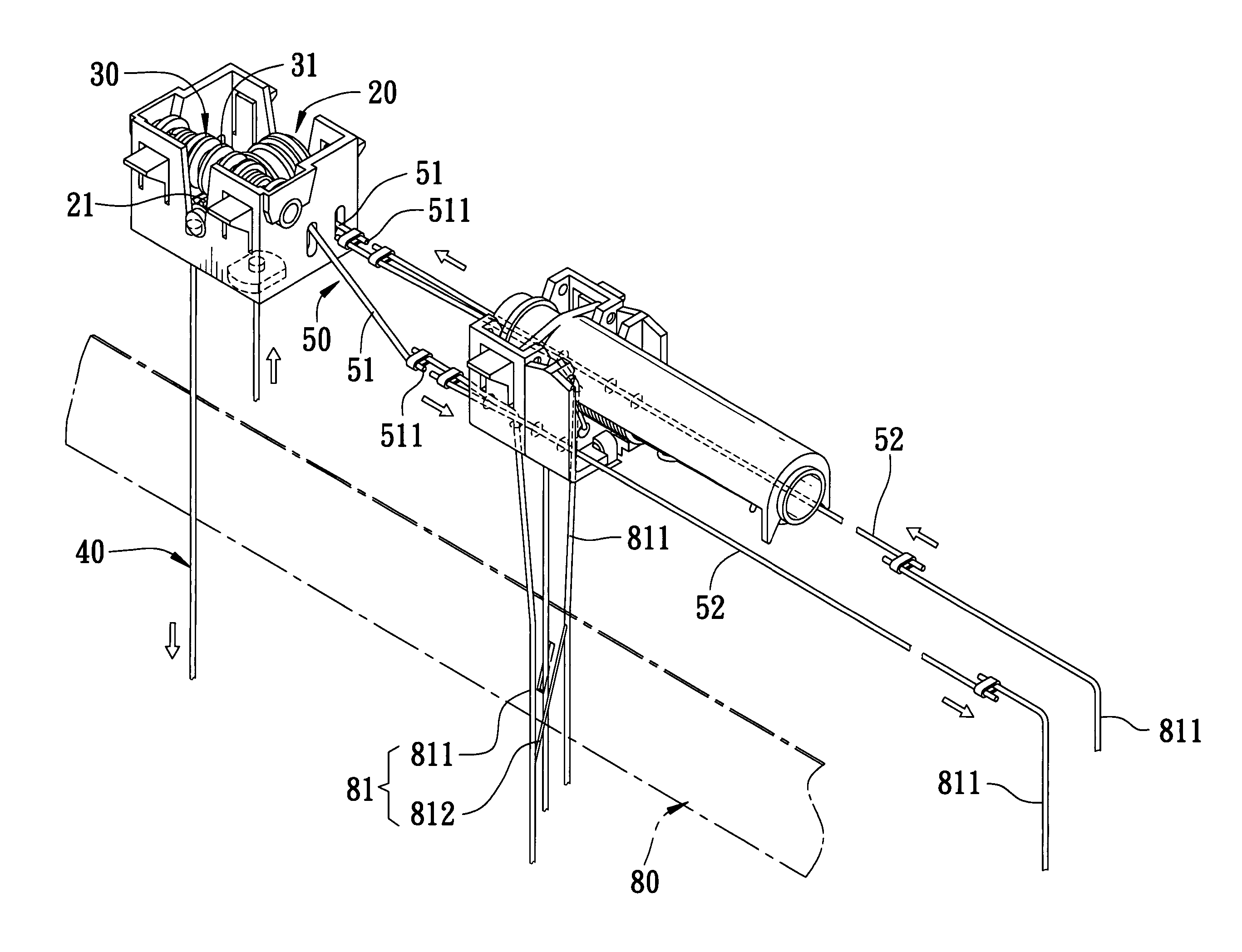
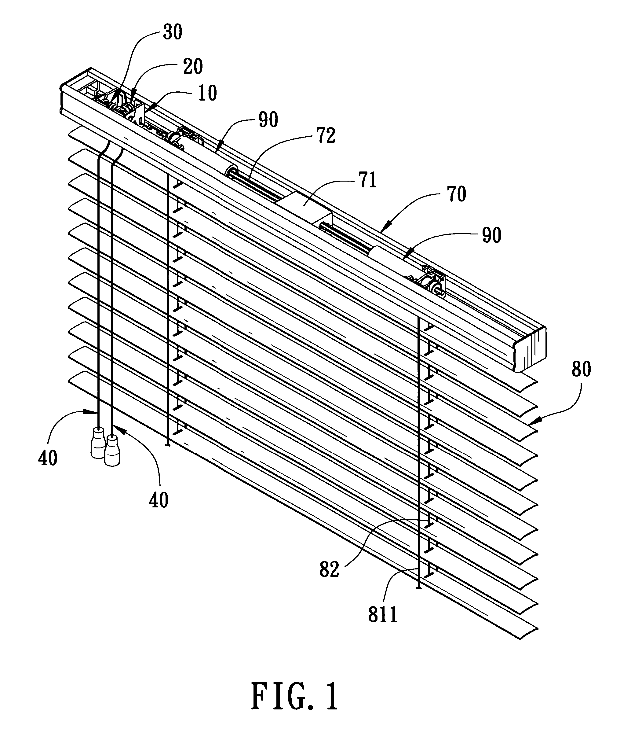
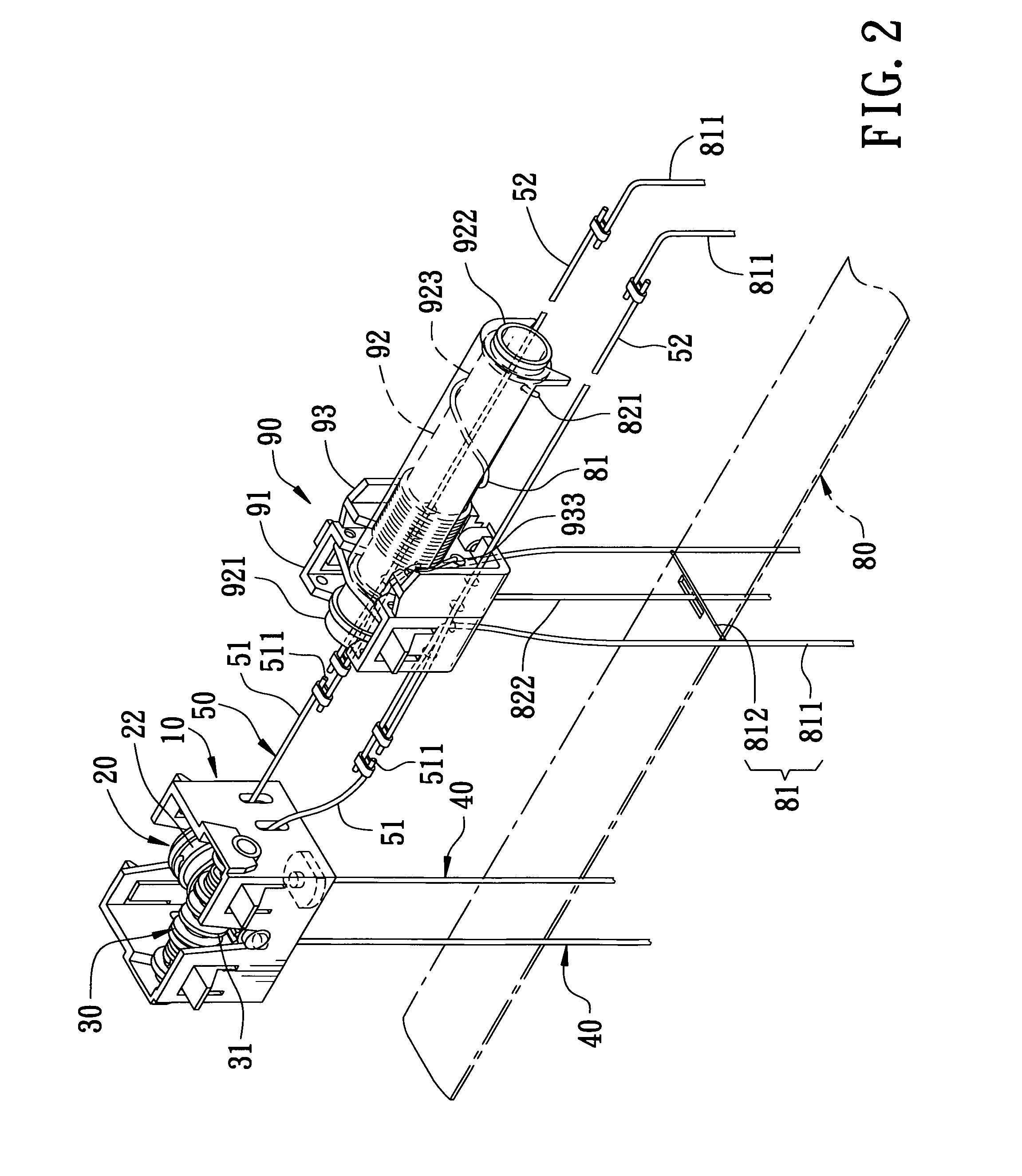
[0013] A first embodiment of an angle adjusting device for blind slats in the present invention, specially applied to a blind with no pulling ropes and fixed in an upper elongate case 70 for moving up and down a rear hanging rope 811 of a left and a right side support rope unit 81 so as to adjust the angle of each slat 80 supported by a connecting rope 812 of the support rope unit 81. The angle adjusting device, as shown in FIGS. 1, 2 and 3, includes a base 10, a winding shaft 20, a transmitting rod 30, two pulling ropes 40, and a winding string 50.

[0014] The base 10 is fixed in one side of the upper elongate case 70.

[0015] The winding shaft 20 is pivotally connected with the base 10, composed of a worm gear 21 on one side and a winding stage 22 on the other side.

[0016] The transmitting rod 30 is pivotally connected to the base 10, composed of a worm 31 engaging the worm gear 21 , rotating the winding shaft 20 clockwise or counterclockwise, and two winding members 32 separated by...


PUM


Abstract

An angle adjusting device for blind slats includes a base fixed in an upper elongate case, a winding shaft pivotally connected to the base and rotatable clockwise or counterclockwise by a controlling member, and a string wound on the winding shaft having two ends extending out of a first end of the base. Then, the two ends of the string are connected respectively with two hanging ropes of a support rope unit so that the angle-adjusting device may be handled for easily adjusting the angle of the blind slats.

Description

BACKGROUND OF THE INVENTION [0001] 1. Field of the Invention [0002] This invention relates to a blind, particularly to an angle-adjusting device for blind slats easily assembled with its cost lowered substantially. [0003] 2. Description of the Prior Art [0004] Conventional blinds, especially Venetian ones, are generally provided with an angle adjusting device fixed in an upper elongate case of blind slats. The conventional angle adjusting device is composed of a base, a winding shaft pivotally deposited on the base, two pulling ropes or a control rod for rotating the winding shaft clockwise or counterclockwise, a rotating shaft fixed with the winding shaft and extending through and fixed with plural stabilizing members that are respectively connected with the upper ends of the two hanging ropes of the support rope set. Thus when a user pulls one of the pulling ropes, the winding shaft and the rotating shaft together with the stabilizing members synchronously rotate clockwise or coun...

Claims


Application Information

Patent Timeline
IPC IPC(8): E06B9/30
CPCE06B9/322
Inventor NIEN, MINGYU CHE, WENYAO, CHANG CHIN
Owner NIEN MADE ENTERPRISE CO LTD
Why Eureka
Eureka Blog
Learn More