Output buffer circuit

a buffer circuit and output circuit technology, applied in pulse generators, pulse techniques, instruments, etc., can solve the problems of transmission line loss, waveform deterioration, and increase current consumption, so as to reduce jitter and increase current consumption

Inactive Publication Date: 2007-03-15
RENESAS ELECTRONICS CORP
View PDF9 Cites 19 Cited by
  • Summary
  • Abstract
  • Description
  • Claims
  • Application Information

AI Technical Summary

Benefits of technology

The present invention controls the output resistance during certain operations to reduce jitter while maintaining low power consumption. This results in improved performance without adding any extra costs or complexity.

Problems solved by technology

The technical problem addressed in this patent text relates to improving the performance and efficiency of CML driver circuits while reducing their reliance on external components like constant current sources. Another issue discussed is how to maintain optimal waveform quality when transmitting signals through wired networks, particularly at higher speeds and longer distances. Additionally, the text discusses the importance of preemphasis functions in ensuring proper operation of the receiver's synchronization process during initial stages of communication.

Method used


Image

  • Output buffer circuit
  • Output buffer circuit
  • Output buffer circuit

Examples


Embodiment Construction

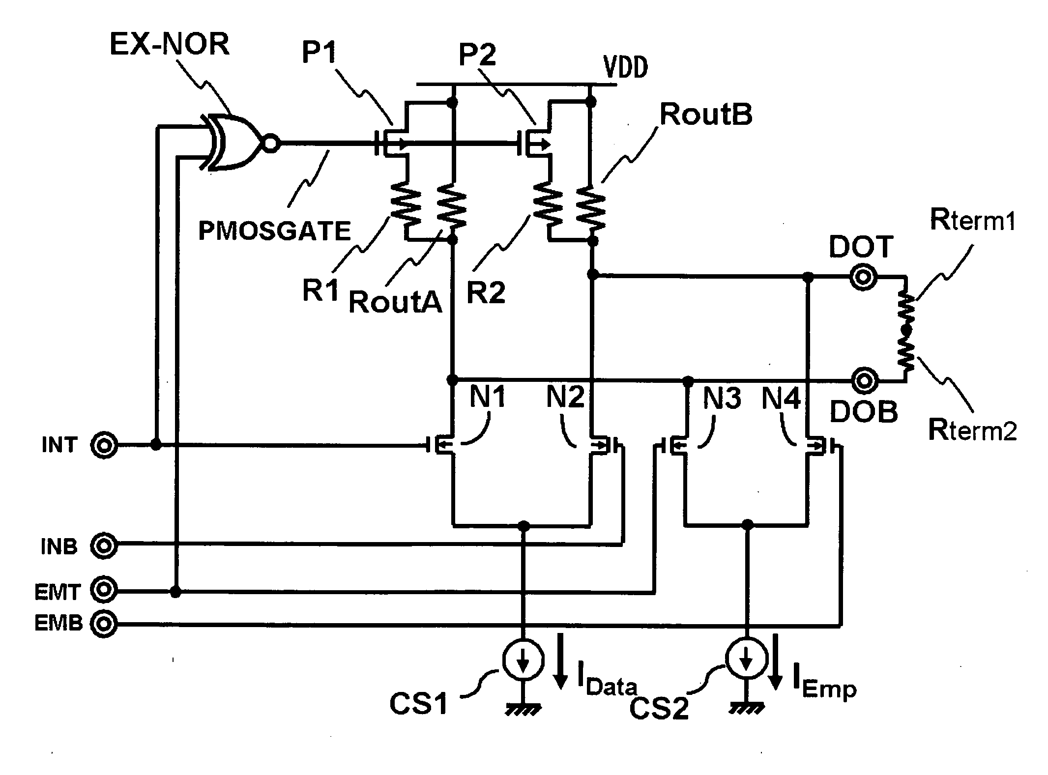
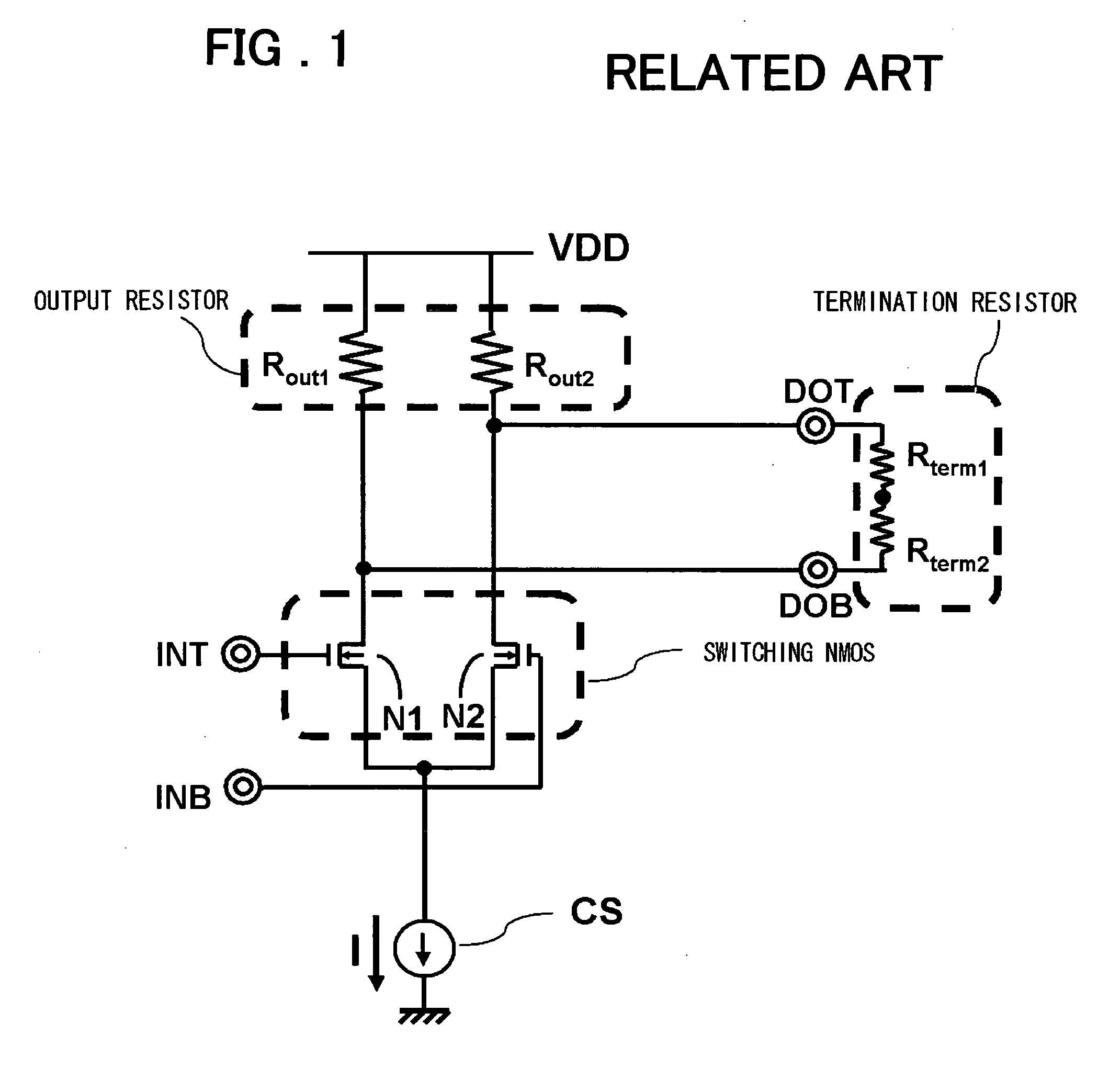
[0082] Referring to the drawings, the present invention will now be described in further detail. The output buffer circuit of the current mode logic, according to the present invention, includes an output resistor between an output pair of a differential circuit and a power supply and has a preemphasis function emphasizing the amplitude when the logic of an output signal undergoes a transition. The output buffer circuit performs switching control so that, at the time of preemphasis, the resistance value of the output resistor will be relatively larger. After the preemphasis, when the output signal is at the same logic as that to which the output signal has transitioned, deemphasis is performed for decreasing the amplitude emphasized. At this time, switching control is exercised so that the resistance value of the output resistor will become relatively smaller. More specifically, the output buffer circuit includes variable resistance elements (P1 and P2 of FIG. 9 and N1 and N2 of FIG...


PUM


Abstract

Disclosed is an output buffer circuit including a first differential transistor pair for differentially receiving a data signal from a differential input pair; and a second differential transistor pair for differentially receiving an emphasis data signal from another differential input pair; a pair of output resistor circuits via which the drains of first and second differential transistor pairs are connected to a power supply, said output resistor circuits each including a transistor; and a logic circuit adapted for receiving the data signal and the emphasis signal and for supplying a control signal which is of first and second values at the time of preemphasis and at other times to the transistors of the output resistor circuit, wherein the output resistance is relatively made larger at the time of emphasis, while being relatively smaller at the time of deemphasis.

Description


Claims


Application Information

Patent Timeline
Owner RENESAS ELECTRONICS CORP
Why Eureka
Try Eureka