
Antenna for dual band operation

a dual-band operation, antenna technology, applied in the structure of radiating elements, elongated active elements, resonance antennas, etc., can solve the problems of short helical antennas, adversely affecting users, damage to monopole antennas,

Inactive Publication Date: 2007-03-15
SAMSUNG ELECTRONICS CO LTD
View PDF5 Cites 20 Cited by
  • Summary
  • Abstract
  • Description
  • Claims
  • Application Information

AI Technical Summary

Benefits of technology

[0015] An aspect of the present general inventive concept is to provide a compact dual band antenna that can be installed inside a portable terminal and have an improved radiation pattern and improved efficiency.

Problems solved by technology

Also, the monopole antennas may be damaged by external impacts.
The helical antennas are shorter than the monopole antennas and may be damaged by external impacts.
Also, the external antennas are positioned above heads of users during the use of the portable terminal, and thus electric waves may adversely affect the users.
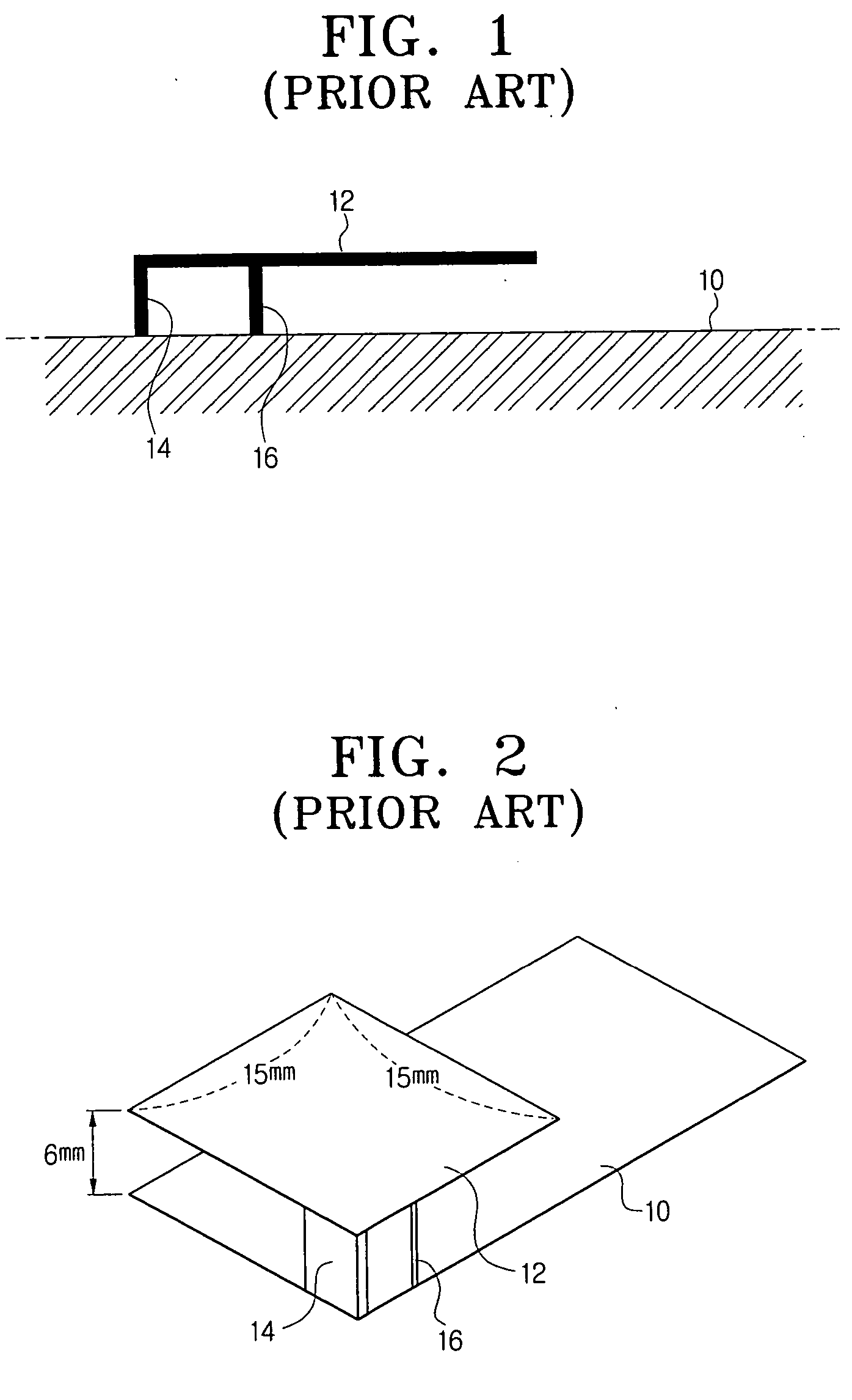
There is a limit to how compact and light a conventional IFA can be in terms of a gap between a radiator and a ground unit, sizes of the radiator and the ground unit, and the like.
Also, a process of producing the conventional IFA is complicated due to structures of the ground unit and a feeder.
However, the conventional IFA still has problems to be overcome.

Method used


Image

  • Antenna for dual band operation
  • Antenna for dual band operation
  • Antenna for dual band operation

Examples


Embodiment Construction

[0039] Certain exemplary embodiments of the present invention will be described in greater detail with reference to the accompanying drawings.

[0040] In the following description, same drawing reference numerals are used for the same elements even in different drawings. The matters defined herein are described at a high-level of abstraction to provide a comprehensive yet clear understanding of the invention. It is also to be noted that it will be apparent to those ordinarily skilled in the art that the present invention is not limited to the description of the exemplary embodiments provided herein.

[0041] Hereinafter, a planar dual band antenna according to the present invention will be described with reference to the attached drawings. In other words, the present invention suggests a 2-dimensional dual band antenna instead of a conventional 3-dimensional IFA.

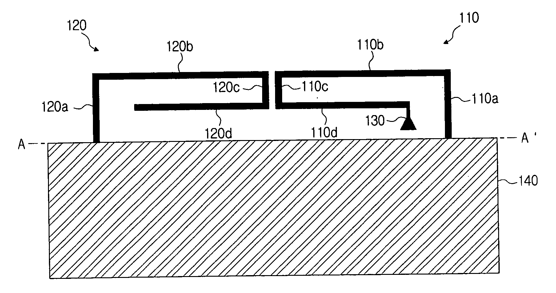
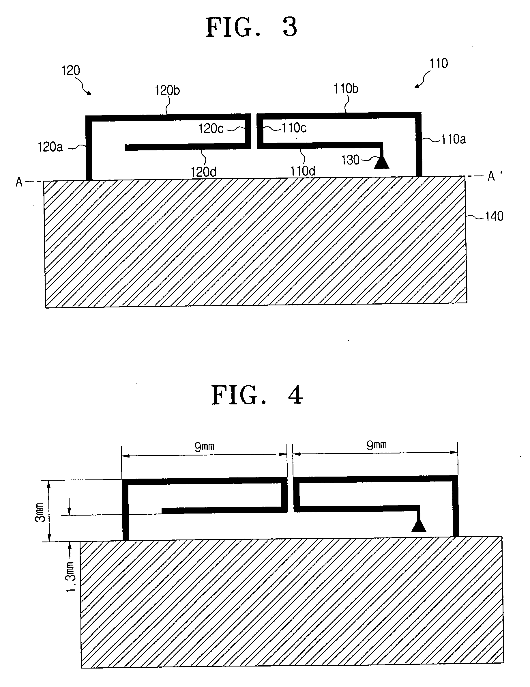
[0042]FIG. 3 is a cross-sectional view of a dual band antenna according to an exemplary embodiment of the present invention....


PUM


Abstract

Provided is a dual band antenna including: a ground surface; a feeder feeding a predetermined current; an induction radiator including one end connected to the ground surface and the other end connected to the feeder; and a parasitic radiator including an end connected to the ground surface and the other end opened. An antenna having a smaller size than an existing IFA mainly used as an internal antenna in a portable terminal can be provided through the dual band antenna including the induction radiator and the parasitic radiator.

Description

CROSS-REFERENCE TO RELATED APPLICATIONS [0001] This application claims the priority from Korean Patent Application No. 2005-85120, filed Sep. 13, 2005, in the Korean Intellectual Property Office, the disclosure of which is incorporated herein by reference. BACKGROUND OF THE INVENTION [0002] 1. Field of the Invention [0003] The present invention relates to an antenna for a dual band operation, and more particularly, to a planar dual band antenna capable of efficiently using an internal space of a portable terminal and improving a radiation pattern and efficiency thereof. [0004] 2. Description of the Related Art [0005] Portable terminals refer to cellular phones or personal digital assistants (PDAs) with which users can transmit and / or receive data during their movements. [0006] Examples of antennas used in conventional portable terminals include external antennas. The external antennas are positioned in external spaces of the portable terminals and classified into monopole antennas a...

Claims


Application Information

Patent Timeline
Patent Type & Authority Applications(United States)
IPC IPC(8): H01Q1/38H01Q5/10
CPCH01Q5/378H01Q9/42H01Q5/10H01Q1/24H01Q9/04
Inventor MOON, YOUNG-MINKIM, YOUNG-EILCHAE, GYOO-SOO
Owner SAMSUNG ELECTRONICS CO LTD
Learn More