Method and system for the three-dimensional surface reconstruction of an object

a three-dimensional surface and object technology, applied in the field of three-dimensional surface reconstruction of objects, can solve the problems of slow data acquisition rate, large data acquisition time, and often impracticality, and achieve fast and accurate 3d reconstruction and labeling. accurate and fast

Inactive Publication Date: 2007-03-15
COGENETENS
View PDF0 Cites 148 Cited by
  • Summary
  • Abstract
  • Description
  • Claims
  • Application Information

AI Technical Summary

Benefits of technology

[0055] Thus, the present invention applies a correspondence method to provide correct line-to-line labeling, providing fast and correct labeling, and with only using two sets of images of the object, and this may provide fast and accurate 3D reconstruction of a surface. In particular, the first stage of the method provides an effective means of correspondence, in only a single data acquisition step, and this correspondence may then be used to perform the line-to-line labeling, allowing the 3D reconstruction to be performed with sub-pixel level of accuracy.

Problems solved by technology

Mechanical systems, while providing accurate 3D data for an objects, rely on mechanical contact between a probe and the object, and only one surface point at a time is measured, which results in a very slow, and often impractical, data acquisition rate.
However, this method also suffers from a long acquisition time, which can also introduce errors if there is any unknown movement between the camera and the object during this time.
While acquisition time is fast, it is difficult to provide matching between the lines in the image taken by the camera and the illumination grid, because there is an ambiguity as to which line in the illumination grid a particular reflected line corresponds to.
This is particularly problematic when the object is itself complex and comprises sharp edges or steep surfaces, as is often the case for manufactured items.
However, such a method requires multiple data acquisition steps, and also suffers from relatively large data acquisition time to obtain the 3D structure of an object.
Since the spatial neighborhood cannot always be recovered in the image, the decoding stage of the method can become problematic, and errors can arise.

Method used


Image

  • Method and system for the three-dimensional surface reconstruction of an object
  • Method and system for the three-dimensional surface reconstruction of an object
  • Method and system for the three-dimensional surface reconstruction of an object

Examples


Embodiment Construction

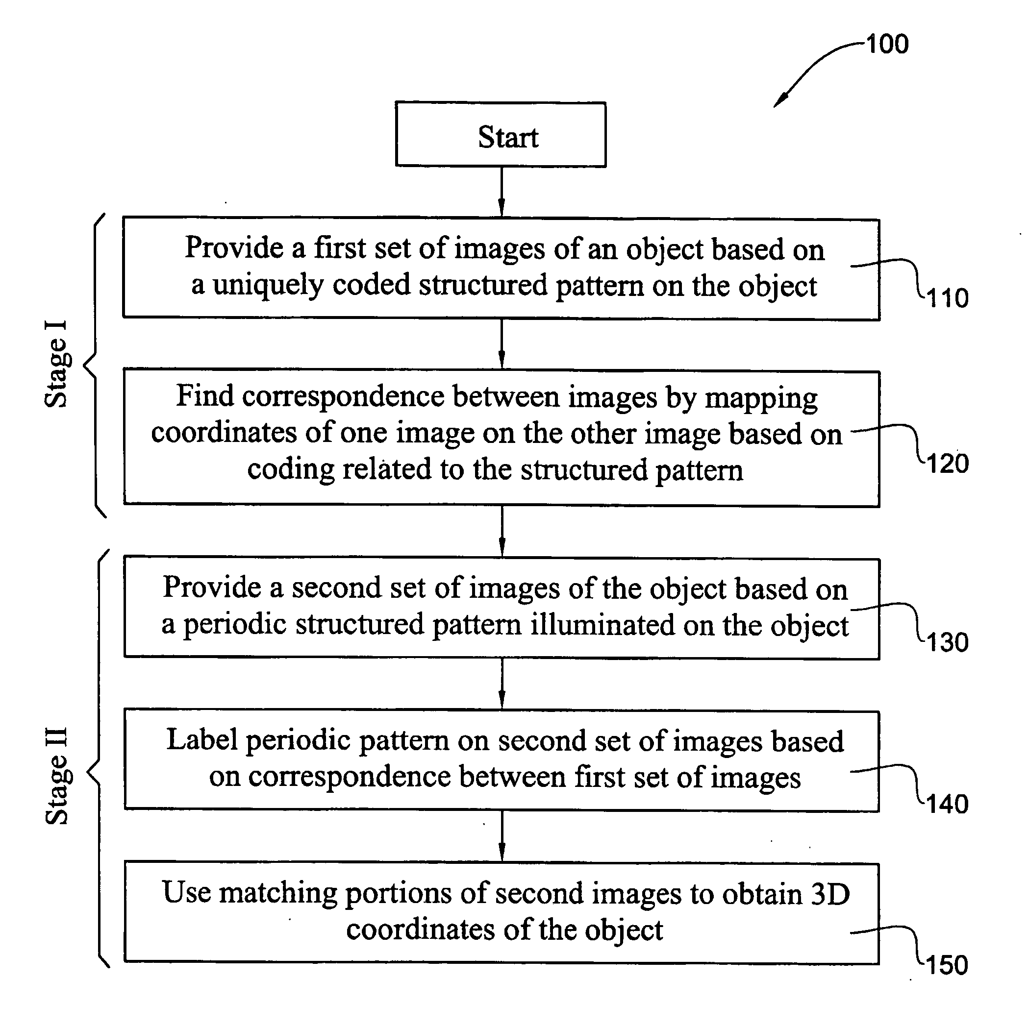
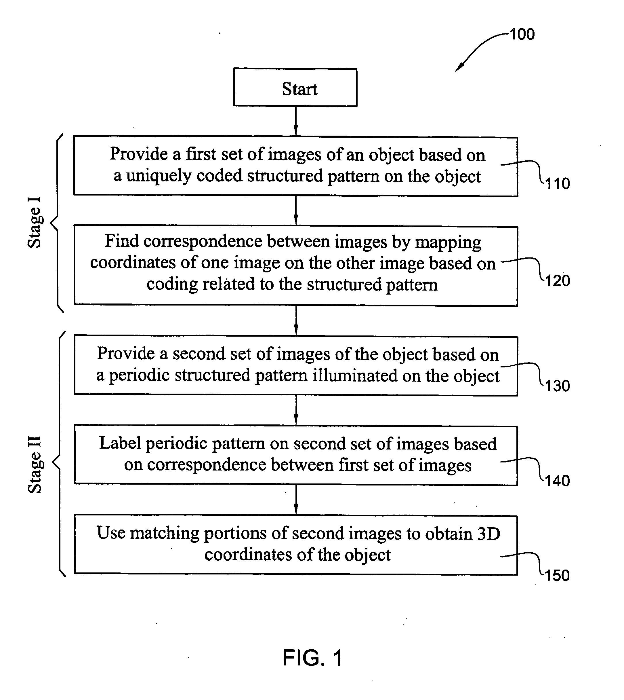
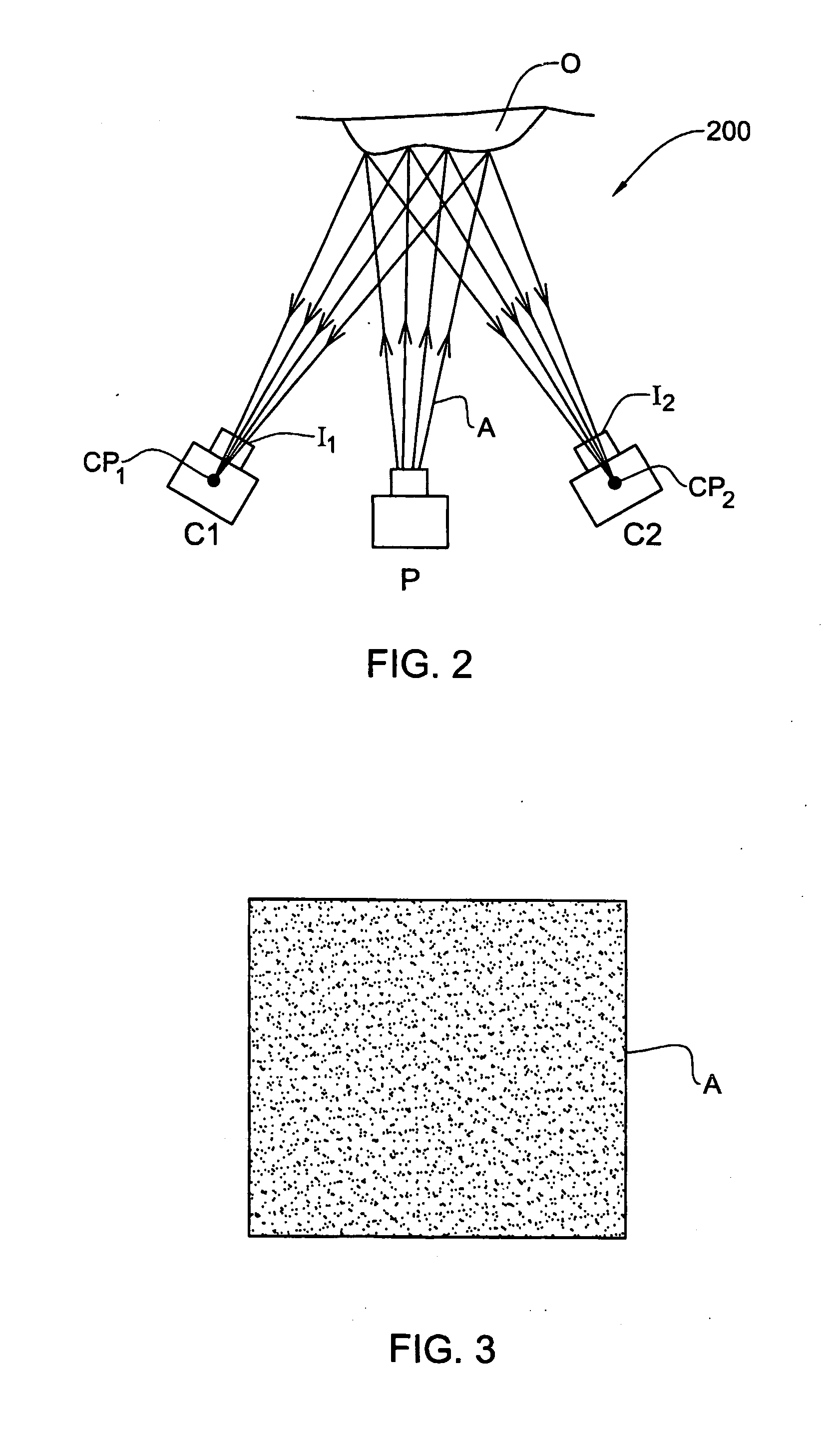
[0069] An embodiment of the method of the invention, generally designated with the reference numeral 100, is illustrated in FIG. 1. In a first stage, Stage I, of the method, and also referring to FIGS. 2, 3 and 4, an object O is illuminated with a structured illumination, such that a unique coding (light pattern) may be concentrated in a single illumination. As illustrated schematically in FIG. 3, such a structured illumination typically comprises spatial coding in the form of a random or quasi random pixel pattern, A, such that preferably each matrix of [n×m] pixels in the pattern is unique. In this embodiment, the pixel pattern A is essentially a two-dimensional gray scale, wherein the pixels are colored black or white. The distribution of black and white pixels may be random. Alternatively, the distribution may be “quasi-random”, i.e., specifically designed so that for any matrix of [n by m] pixels within the grid (pattern), there is a unique permutation of white and black pixels...


PUM


Abstract

A method for reconstructing 3D surface structure of an object uses a two stage approach. In the first stage, a first set of images is obtained, and a spatial coding technique, such as a random grid, is used for correspondence mapping of coordinates from a first image to a second image of an object, and the images are obtained at different angles with respect to the object. In the second stage, a second structured illumination, typically comprising a striped grid, is used to obtain a second set of images, typically comprising two further images of the object. The mapping provided by the first stage provides proper labeling of the grid between these two images of the second set, and enables accurate matching of elements between these images. Triangulation or epipole methods can then be used for obtaining the 3D coordinates of the surface being reconstructed.

Description

FIELD OF THE INVENTION [0001] This invention relates to a system and method for the three-dimensional surface reconstruction of an object, in particular at least partially based on structured illumination techniques. The invention also relates to the labeling of elements between two images of an object or scene. BACKGROUND OF THE INVENTION [0002] The determination of a three-dimensional (3D) shape of an object is of important significance in many fields. For example, in the field of dimensional measurement of manufactured objects, accurate measurement of a number of predetermined dimensions and / or the surface coordinates of such objects can provide an important tool for determining the accuracy of the manufacturing process. [0003] Systems and methods for such 3D shape determination, particularly for industrial applications, have followed two main paths: mechanical and optical. Mechanical systems, while providing accurate 3D data for an objects, rely on mechanical contact between a p...

Claims


Application Information

Patent Timeline
Patent Type & Authority Applications(United States)
IPC IPC(8): G06T17/20G06T15/20G06T17/00G06T15/30G06T15/10G01B11/25G06T7/00G06V10/145G06V10/147
CPCG01B11/2513G06K9/2036G06T7/0065G06T7/0057G06K9/209G06T7/521G06T7/55G06V10/145G06V10/147
Inventor ALBECK, DANSEGEV, AVNERSHALOM, TAMIR
Owner COGENETENS
Why Eureka
Try Eureka