
Magnetic tape cartridge

a magnetic tape and cartridge technology, applied in the field of magnetic tape cartridges, can solve the problems of inability of detectors to detect magnetic tape cartridges, magnetic tape cartridges not to be carried with the upper surfaces of the upper halves, and inability to detect security tags

Active Publication Date: 2007-03-15
FUJIFILM HLDG CORP +1
View PDF10 Cites 20 Cited by
  • Summary
  • Abstract
  • Description
  • Claims
  • Application Information

AI Technical Summary

Benefits of technology

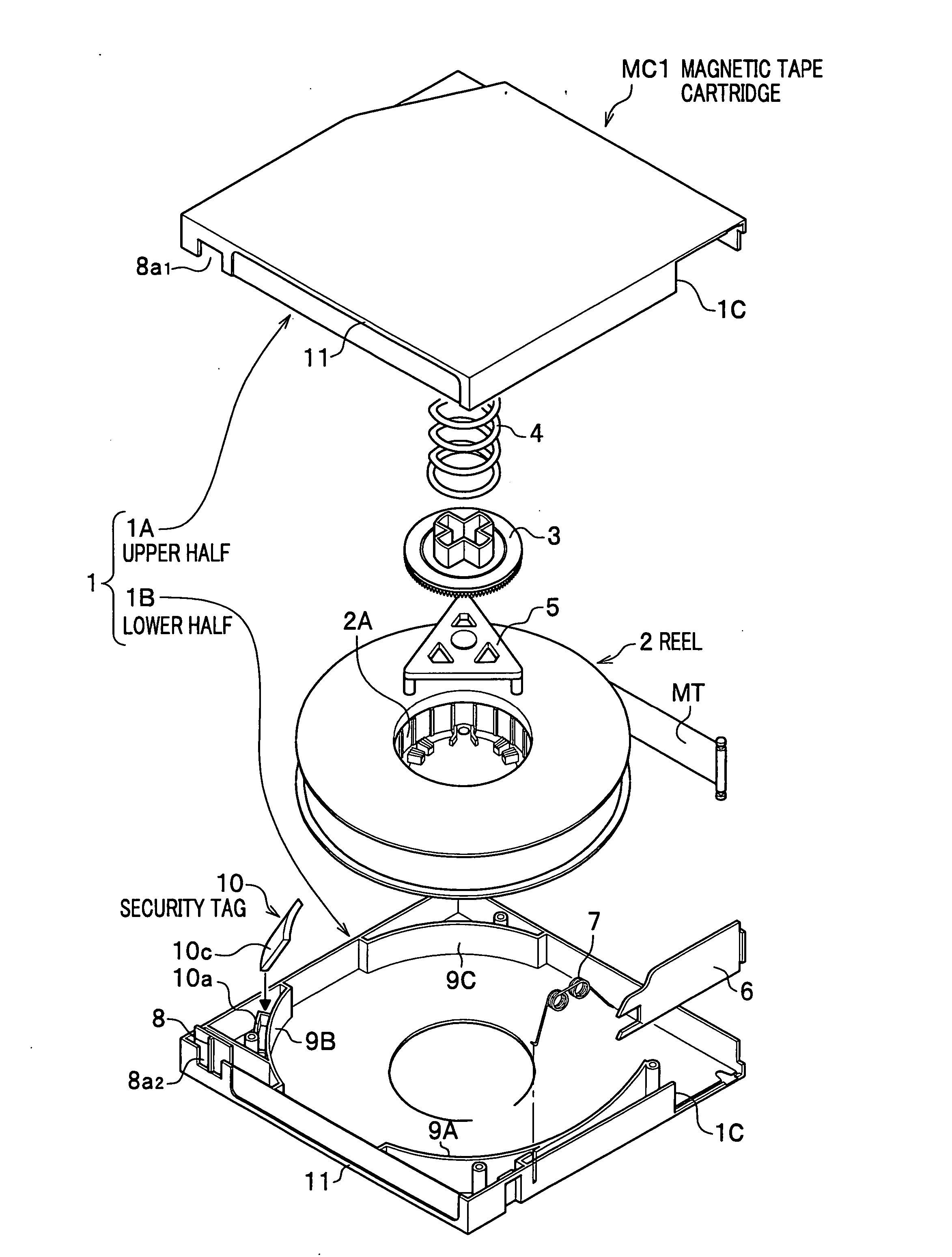
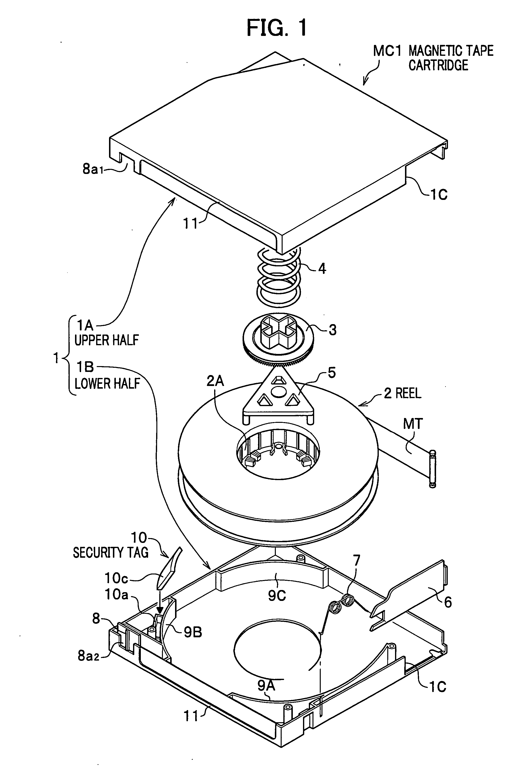
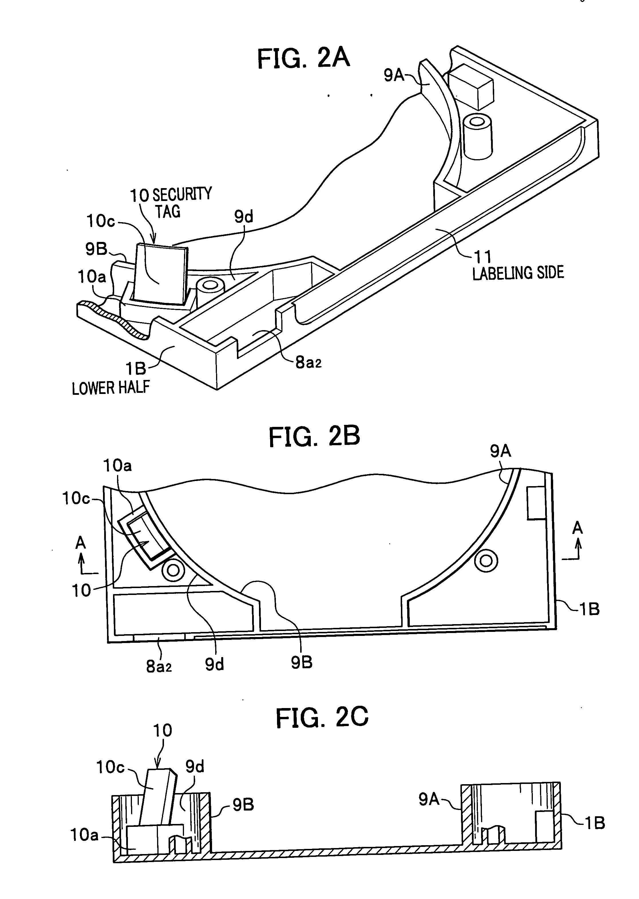
[0014] In the magnetic tape cartridge, the security tag which the external detector can detect is arranged behind the outer surface of the case where the labeling side is provided. In addition, the security tag is arranged so as to face obliquely upward. As a result, the detector can more surely detect the security tag.

Problems solved by technology

Therefore, when the security tag is detached, a detector cannot detect the magnetic tape cartridge even though the detector is set in a doorway.
Therefore, the magnetic tape cartridges are not to be carried with the upper surfaces of the upper halves facing a floor even using methods other than the carrier cart.
As a result, the detector may be impossible to detect the security tag since a detection signal from the detector or the like may be blocked depending on methods or ways to carry out the magnetic tape cartridge.

Method used


Image

  • Magnetic tape cartridge
  • Magnetic tape cartridge
  • Magnetic tape cartridge

Examples


second embodiment

[0050]FIG. 4 is a partially cut-away perspective view of a magnetic tape cartridge MC2 according to the present invention.

[0051] As shown in FIG. 4, in the magnetic tape cartridge MC2, an upper half 41A and a lower half 41B are combined to form a case 41. In addition, a supply hub (a reel or a first reel) 42A to which a magnetic tape MT is wound and a take-up hub (a reel or a second reel) 42B are contained inside the case 41.

[0052] In a front side (in an upper right direction in FIG. 4) of the upper half 41 A, a front cover 43 is pivotally attached to the upper half 41A. The front cover 43 protects the magnetic tape MT which runs in front of the case 41 while the magnetic tape cartridge MC2 is not used. Moreover, a slider (not shown) to cover an opening (not shown) into which a driving unit of a tape reader / recorder (a tape drive) is to be inserted is attached in a lower surface of an outside of the lower half 41B so as to be able to slide back and forth.

[0053] In the magnetic tap...

first embodiment

[0056] In addition, in the first embodiment, description has been given to an example where the security tag 10 is installed to the reinforcing rib 9B behind the write protector 8. However, the security tag 10 may be arranged on the outside wall of the reinforcing rib 9A. In this case, the security tag 10 may be also installed by any of installation methods using a tag installation rib 10a, adhesive, double-faced tape, screws, and so on.

[0057] For a magnetic tape cartridge of the present invention, any type of detectors which can detect a security tag built in the magnetic tape cartridge may be employed. For instance, as shown in FIG. 5A, two detectors 51A and 51B which transmit detection signals may be placed to face each other. In this way, a carrier cart, a person who carries out the magnetic tape cartridge, or the like may pass through between the detectors. Moreover, as shown in FIG. 5B, a detector 54 which transmits a detection signal may be placed in an upper portion of a ser...


PUM


Abstract

A magnetic tape cartridge is provided including a case which is formed by an upper half and a lower half which are combined together, a reel to which a magnetic tape is wound, being rotatably contained in the case, a labeling side which is provided in an outer surface of the case, and a security tag which an external detector can detect, in which the security tag is arranged behind the labeling side so as to face obliquely upward.

Description

CROSS REFERENCE TO RELATED APPLICATIONS [0001] This application claims the foreign priority benefit under Title 35, United States Code, §119(a)-(d) of Japanese Patent Application No. 2005-186766, filed on Jun. 27, 2005 in the Japan Patent Office, the disclosure of which is herein incorporated by reference in its entirety. BACKGROUND OF THE INVENTION [0002] 1. Field of the Invention [0003] The present invention relates to a magnetic tape cartridge, and more specifically, to a magnetic tape cartridge which a detector can surely detect. [0004] 2. Description of the Related Art [0005] In companies, organizations, institutions, and so on which handle a large amount of data or very important data such as personal information which require security protection, the data are saved in a large capacity of recording medium so as to be backed up. Thus, it is possible to prevent loss of the data. A magnetic tape cartridge is used as the recording medium to back up the data due to its large storag...

Claims


Application Information

Patent Timeline
IPC IPC(8): G11B23/107G08B13/14
CPCG11B23/107G08B13/2445
Inventor TADA, NOBUYUKIHIGASHI, NOBUAKI
Owner FUJIFILM HLDG CORP
Learn More