Optical disc apparatus and recording power determining method thereof

Inactive Publication Date: 2005-01-18
PANASONIC CORP
View PDF4 Cites 63 Cited by
  • Summary
  • Abstract
  • Description
  • Claims
  • Application Information

AI Technical Summary

Benefits of technology

It is an object of the present invention to provide a recording method capable of surely detecting the unused area for test recording when the test recording is carried out in a write-once type optical discs.

Problems solved by technology

In such event, since the area once recorded cannot be reused in the write-once type optical disc, it is necessary to search for the unused area for carrying out the test recording.
However, because by the conventional technique, in the area where even though recording was carried out, the recording was not satisfactory due to, for example, stains of light pickup, etc., there was a problem in which changes of reflecting light quantity were small.

Method used


Image

  • Optical disc apparatus and recording power determining method thereof
  • Optical disc apparatus and recording power determining method thereof
  • Optical disc apparatus and recording power determining method thereof

Examples


Embodiment Construction

Referring to the accompanied drawings, preferred embodiments of the optical disc apparatus according to the present invention will be described in detail hereinafter.

<1. Configuration of the Optical Disc Apparatus>

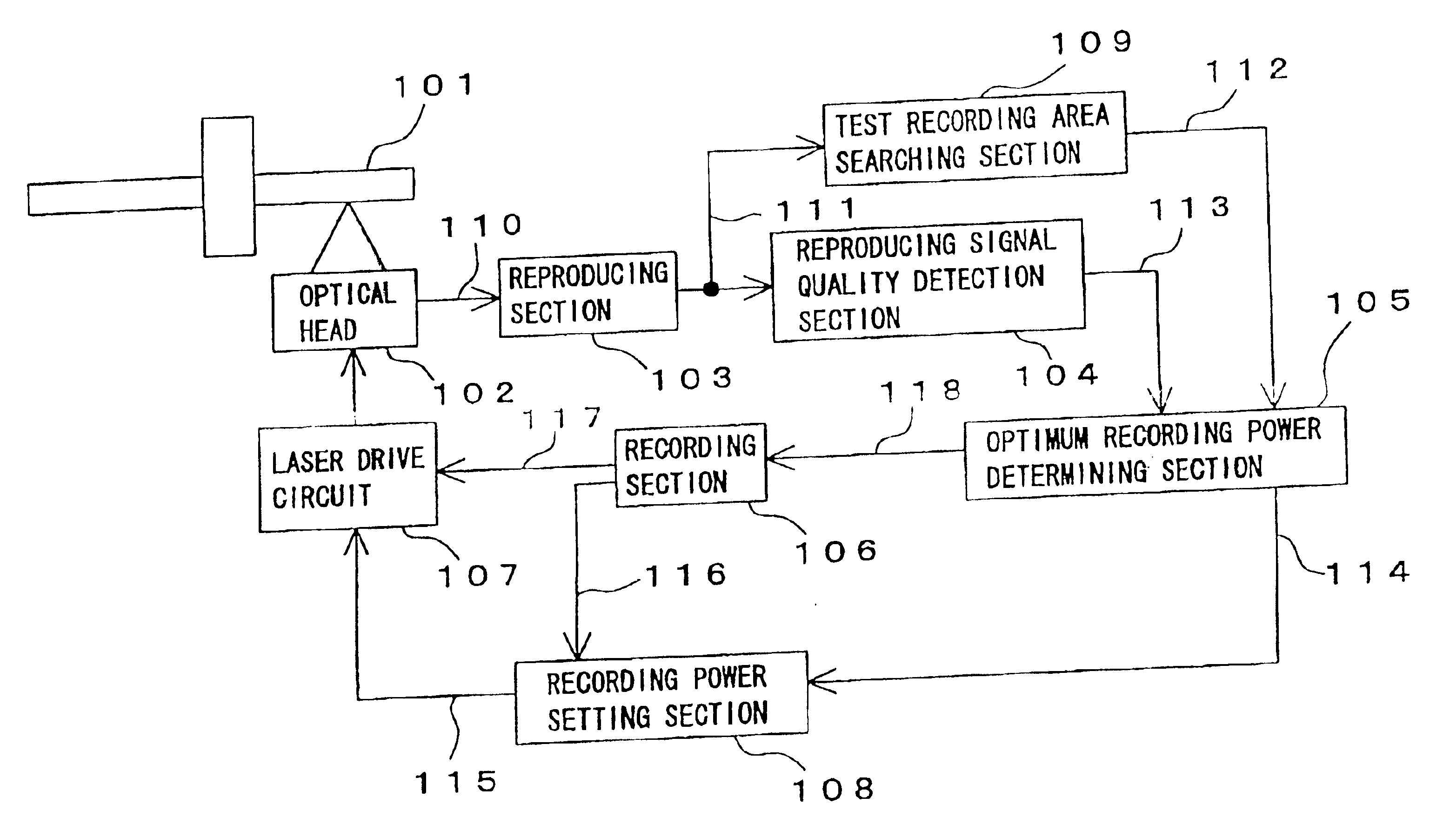
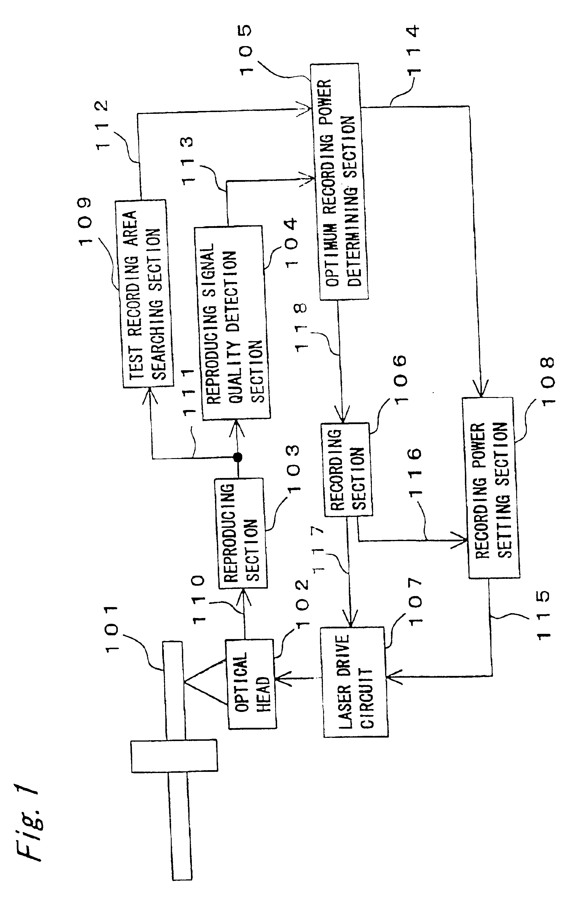
FIG. 1 shows the configuration of the optical disc apparatus in one embodiment according to the present invention. In FIG. 1, the optical disc apparatus is an apparatus for recording information to an optical disc 101, and includes an optical head 102, reproducing section 103, reproducing signal quality detection section 104, optimum recording power determining section 105, recording section 106, laser drive circuit 107, recording power setting section 108 and test recording area searching section 109. The optical disc 101 referred to here is a write-once optical disc which can record information only once to the same place.

<2. Data Structure of Optical Disc>

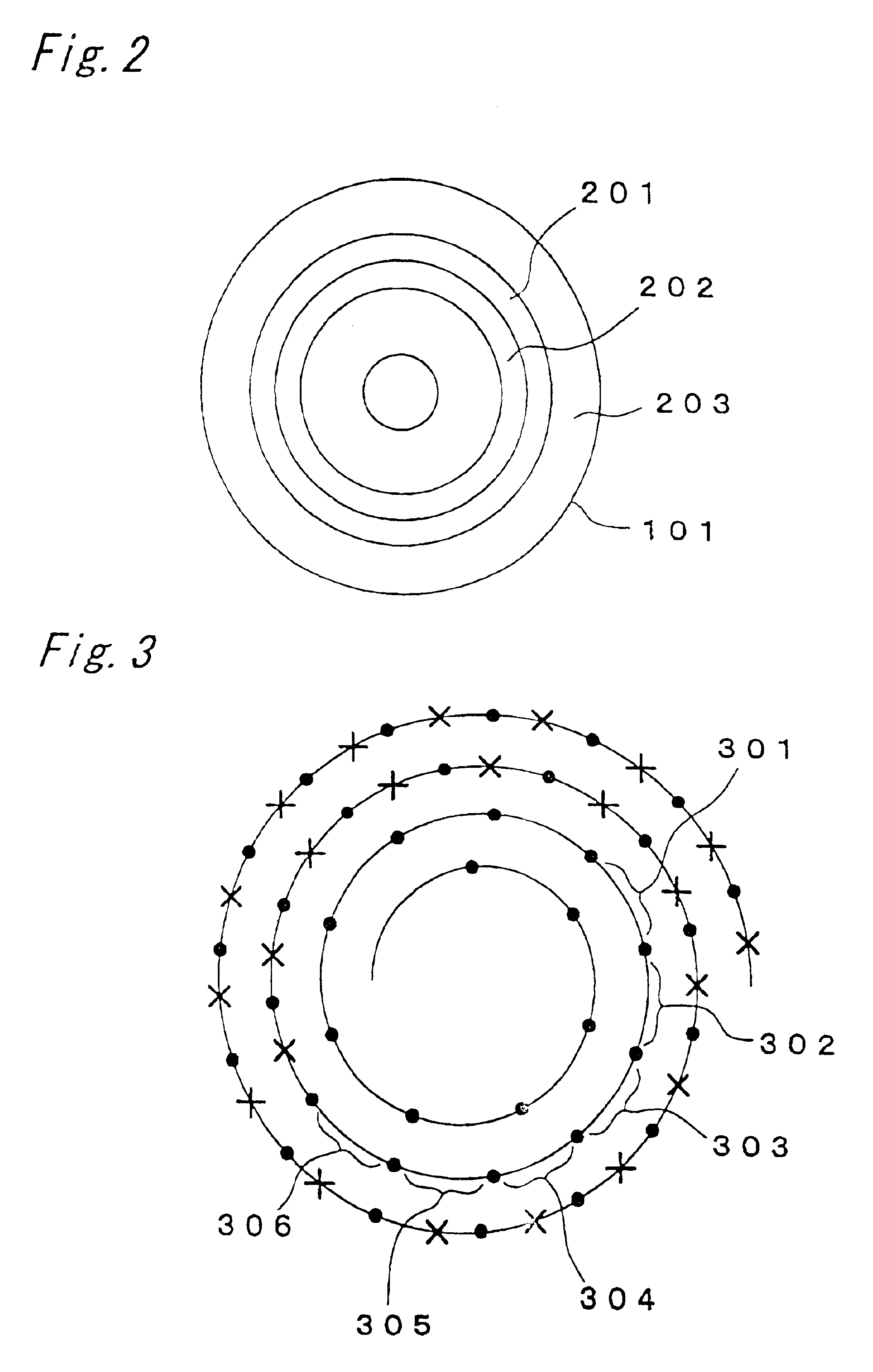
FIG. 2 is a diagram showing areas logically formed on the optical disc 101 in the present embodiment. As s...


PUM


Abstract

A method of determining a recording power used to record information to an optical disc, includes carrying out test recording which records predetermined data to a predetermined area of the optical disc to determine the recording power, and recording predetermined data with a power equal to or more than the determined recording power to an area adjacent to the predetermined area.

Description

BACKGROUND OF THE INVENTION1. Field of the InventionThe present invention relates to a method of determining optimum recording power in optical disc apparatus for recording information by irradiating optical discs with a laser beam.2. Related ArtOptical discs have been extensively developed as a means for recording a large volume of data, and for one of them, there is a write-once type optical disc which utilizes the state change of organic pigment and can record information once only in one same place. In the optical disc that uses organic-based pigment for recording film, the vapor pressure in the vicinity of the surface of the recording portion is raised by irradiation of an optimum light beam and presses to expand the melted portion to the periphery to form a pit.In recording information to such a kind of optical disc, it is important to optimize the irradiation power of light beam, and accordingly a method of carrying out test recording in the predetermined area of the optical ...

Claims


Application Information

Patent Timeline
IPC IPC(8): G11B7/125G11B7/00G11B5/09G11B7/0045
CPCG11B7/00736G11B7/1267G11B7/126G11B7/00458G11B2007/0013
Inventor SHOJI, MAMORUTASAKA, SHUICHIIGAMI, EIICHIKOISHI, KENJI
Owner PANASONIC CORP
Why Eureka
Try Eureka