Eureka AIR delivers breakthrough ideas for toughest innovation challenges, trusted by R&D personnel around the world.

Electric stapler

Active Publication Date: 2010-12-02
MAX CO LTD
View PDF24 Cites 2 Cited by
  • Summary
  • Abstract
  • Description
  • Claims
  • Application Information

AI Technical Summary

Benefits of technology

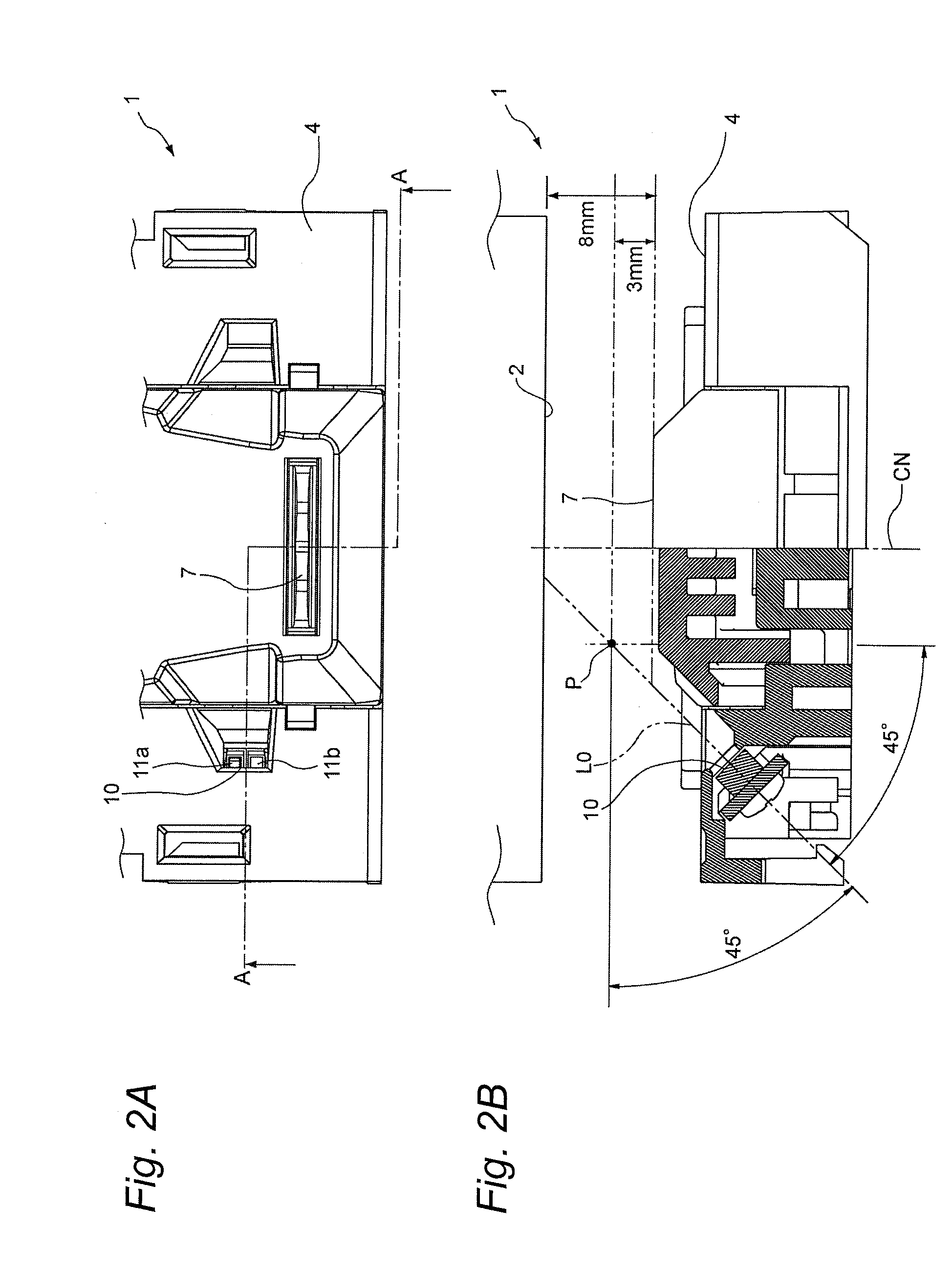
[0015]Illustrative aspects of the present invention provide an electric stapler which can surely detect that a paper bundle is inserted fully into a clincher position before the electric stapler carries out a paper bundle binding operation.

Problems solved by technology

However, to dispose the photo sensor on the deep side of the clincher position, actually, is not easy due to the structure of the electric stapler and, therefore, generally, the photo sensor has been often disposed on an upper-stream side of the clincher position.
On the other hand, in the case that the delaying time is too long, a user can, who judges that the binding processing will not be carried out, can draw out the paper bundle, and thus the binding processing is carried out in a state where no paper bundle exists, resulting in the idle striking of a staple.
However, in the case that a distance from positions of a table, on which the two photo sensors are respectively disposed, to a lower face of a magazine (or, a staple cartridge to be mounted onto the magazine) is short, it is hard to find a difference between the detection point in the photo sensor and the distance to the lower face of the magazine, thereby reducing the sensitivity (the S / N ratio) of the photo sensors for the presence or absence of the paper bundle.
Thus, due to interference between the reflected lights (radiation lights) that have been received, it is difficult to detect the presence or absence of the insertion of the paper bundle with high accuracy.

Method used


Image

  • Electric stapler
  • Electric stapler
  • Electric stapler

Examples


first exemplary embodiment

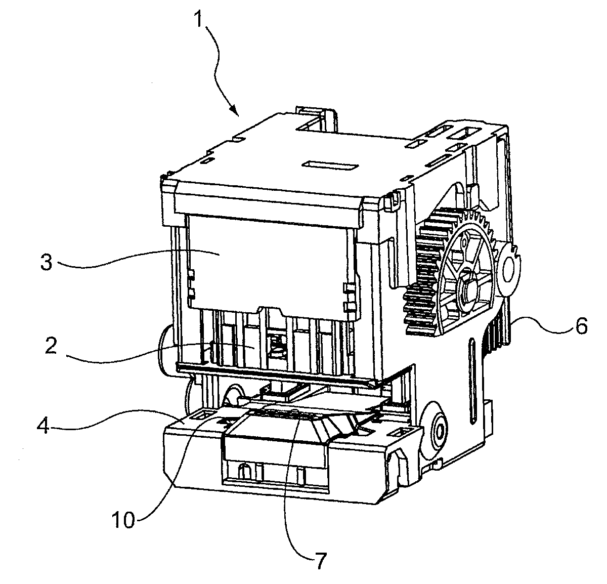
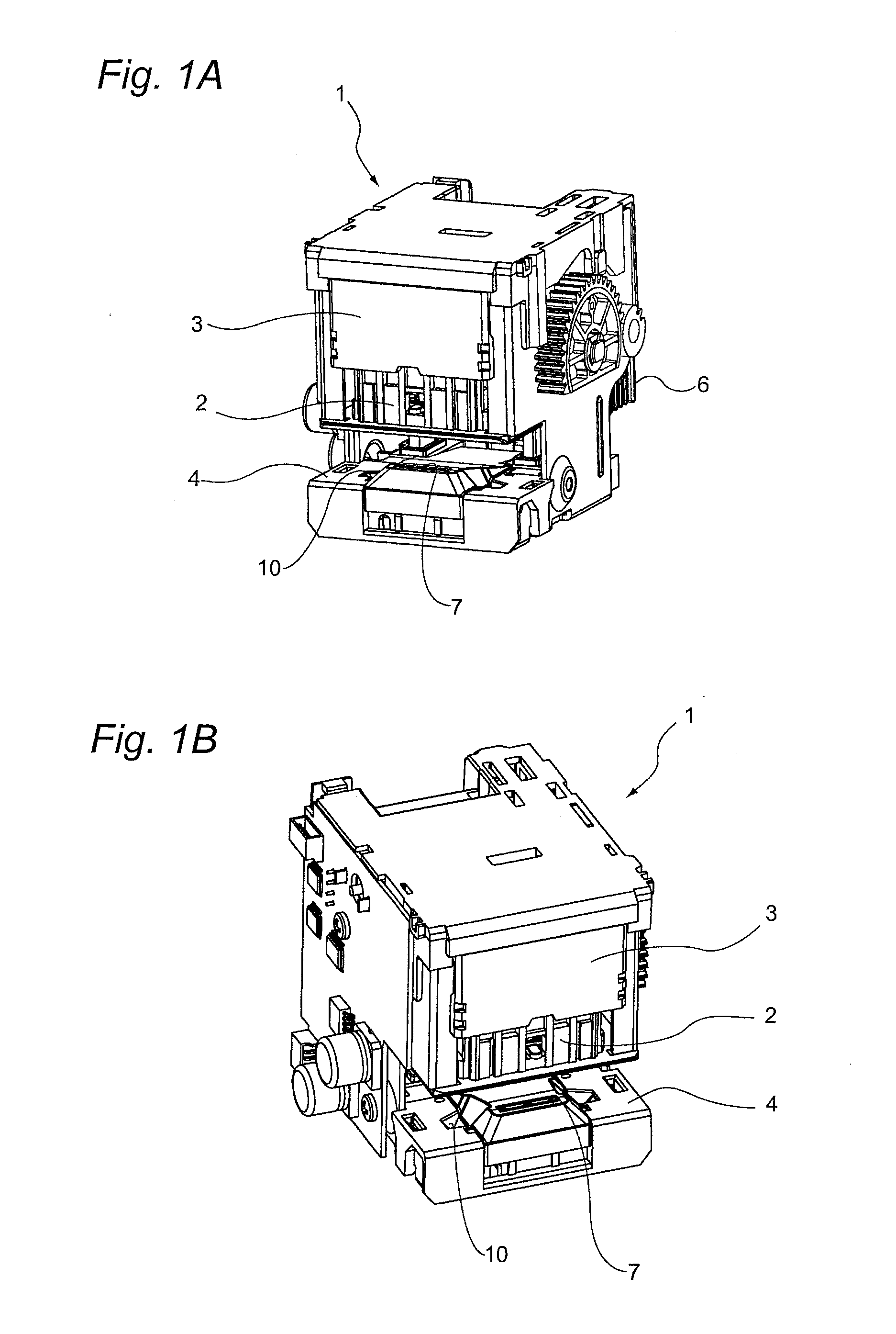
[0037]FIGS. 1A and 1B are respectively perspective views showing an electric stapler according to a first exemplary embodiment.

[0038]The electric stapler 1 includes a magazine 2, a driver unit (driver means) 3, a table (table means) 4, and a motor (not shown).

[0039]The magazine 3 is disposed in a central portion of the electric stapler 1 and has a function to hold a staple cartridge 6. When the staple cartridge 6 is inserted from a back face side of the electric stapler 1 into the magazine 2, the staple cartridge 6 can be mounted into the magazine 2.

[0040]The driver unit 3 is disposed upwardly of the magazine 2 and is held through a gear (not shown) in such a manner that it is spaced by a given distance from the magazine 2. The driver unit 3 includes a forming plate (not shown) for bending and forming a staple in such a manner that the staple has a U-shaped section, and a driver (not shown) for driving out the staple, which has been bent and formed by the forming plate, in a directi...

second exemplary embodiment

[0056]Next, description will be given below of an electric stapler according to a second exemplary embodiment of the invention. In the electric stapler 1 according to the first exemplary embodiment, description has been given of a case in which only one photo sensor 10 is set on the table 4. However, an electric stapler according to the second exemplary embodiment is different from the electric stapler 1 according to the first exemplary embodiment in that it employs two photo sensors. Here, the parts of the second exemplary embodiments having the same structures as those described in the first exemplary embodiment are given the same designations and thus the detailed description thereof is omitted here.

[0057]As shown in FIGS. 4A and 4B, on a table 4 used in an electric stapler 20 according to the second exemplary embodiment, there are provided two photo sensors 10a and 10b respectively at positions adjacent to left and right sides of a clincher 7. The photo sensors 10a and 10b are r...

third exemplary embodiment

[0070]Now, description will be given specifically of an electric stapler 30 according to a third exemplary embodiment of the invention. Here, the parts of the third exemplary embodiment having the same structures as those described in the first exemplary embodiment are given the same designations and thus the detailed description thereof is omitted here.

[0071]As shown in FIGS. 7A and 7B, two photo sensors 10a and 10b are disposed at two positions which respectively exist adjacent to the left and right sides of the clincher 7 when the table 4 is viewed from the front side thereof. The two photo sensors 10a and 10b are respectively made of a reflection type photo interrupter. Specifically, the photo sensor 10a includes a light emitting portion (first light emitting means) 14a and a light receiving portion 14b (first light receiving means) which are formed integrally with each other; and, the photo sensor 10b includes a light emitting portion (second light emitting means) 15a and a lig...


PUM

PropertyMeasurementUnit
Optical propertiesaaaaaaaaaa

Abstract

An electric stapler includes: a driver for driving leg portions of a staple having a U-shaped section to penetrate the leg portions through a paper bundle; a table including a clincher for bending and forming the penetrated leg portions inwardly, the table for holding the paper bundle between the driver and the table; a motor for moving the table and the driver; a photo sensor for detecting an existence of the paper bundle inserted into a gap between the table and the driver; and a control portion for driving the motor. The photo sensor is disposed on the table in such a manner that a detection point of the photo sensor for detecting the paper bundle exists upwardly of a disposing position of the clincher by inclining an optical axis direction of a radiation light to be emitted from the photo sensor in a direction of the clincher.

Description

[0001]This application claims priority from Japanese Patent Application No. 2009-128859, filed on May 28, 2009, and Japanese Patent Application No. 2009-128860, filed on May 28, 2009, the entire contents of which are hereby incorporated by reference.FIELD OF THE INVENTION[0002]The present disclosure relates to an electric stapler. More specifically, the present disclosure relates to an electric stapler which moves a table unit and a driver unit relative to each other to hold a bundle of sheets between the table unit and driver unit, drives the driver unit to penetrate leg portions of a staple so formed as to have a U-shaped section through a bundle of papers, and drives a clincher included in the table unit to inwardly bend and form the penetrated leg portions of the staple, thereby carrying out a series of binding processings.DESCRIPTION OF RELATED ART[0003]There is known a related-art electric stapler which is used bind a bundle of multiple papers (a paper bundle) using staples. T...

Claims


Application Information

Patent Timeline
IPC IPC(8): B27F7/36B27F7/19
CPCB27F7/21
Inventor MATSUI, TOMOKAZUYAGI, NOBUAKIKAMEDA, FUTOSHICHIGIRA, YOSHIO
Owner MAX CO LTD
Why Eureka
Eureka Blog
Learn More