
Air conditioner and method for assembling the same

Inactive Publication Date: 2007-03-15
FUJITSU GENERAL LTD
View PDF4 Cites 57 Cited by
  • Summary
  • Abstract
  • Description
  • Claims
  • Application Information

AI Technical Summary

Benefits of technology

[0020] Thus, this invention is accomplished in order to solve the above problems. An object of this invention is to provide an air conditioner capable of surely removing dust deposited on a filter and storing the dust thus removed and also carrying out filter cleaning even while air conditioning is executed.
[0021] Further, another object of this invention is to provide a an air conditioner capable of miniaturizing its body by reducing the space for operating the dedusting device.

Problems solved by technology

Usually, since the air conditioner is installed at a high position of a room, the operation of attaching or detaching the filter is troublesome.
In addition, the operation of diligently removing dust deposited on the filter is also troublesome.
However, if the filter is left with dust accumulated, the air flow-rate will be reduced so that the efficiency of thermal conversion is lowered.
In addition, the dust may get mildewed so that a bad smell or house dust which gives rises to allelgic symptoms is attracted.
However, the above conventional air conditioner has the following problems.
However, since the filter is usually made of relatively flexible resin, if its surface is pressed by the cleaning brush, the filter will warp owing to the pressing force of the brush so that the brush cannot be held down on the surface of the filter by uniform force.
Thus, the dust cannot be surely scraped off.
Further, in a conventional air cleaner or air conditioner, where it is installed at a high position, when a dust-collecting filter is detached for its cleaning, dust fell on a user's face or body or hand became dirty and so insanitary.
This presents a problem that its size in the vertical or horizontal direction is increased, thereby making it difficult to reduce the size.
As a result, the air filter may be taken off from the filter guides (guide frames) and so the poor mounting of the air filter by a user may occur.

Method used


Image

  • Air conditioner and method for assembling the same
  • Air conditioner and method for assembling the same
  • Air conditioner and method for assembling the same

Examples


first embodiment

(First Embodiment)

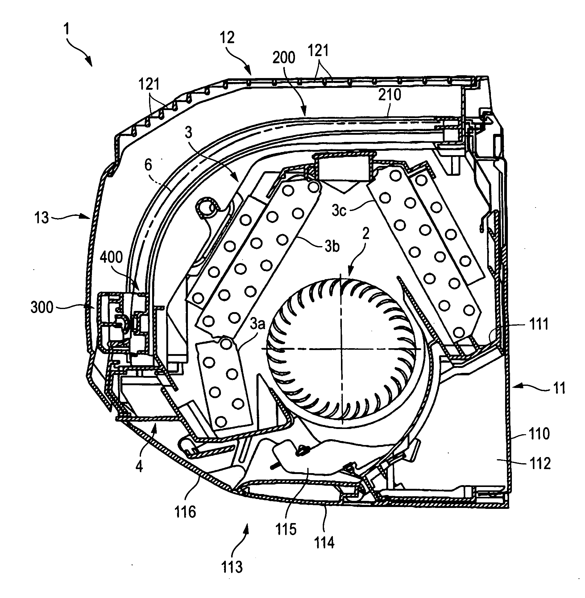
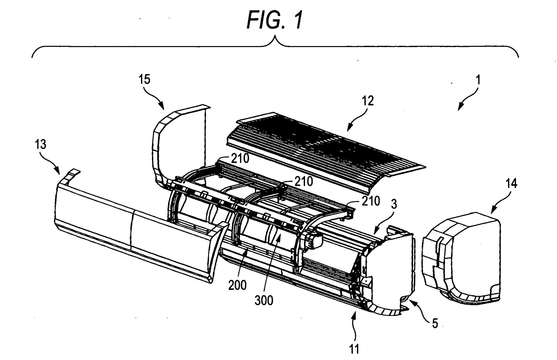
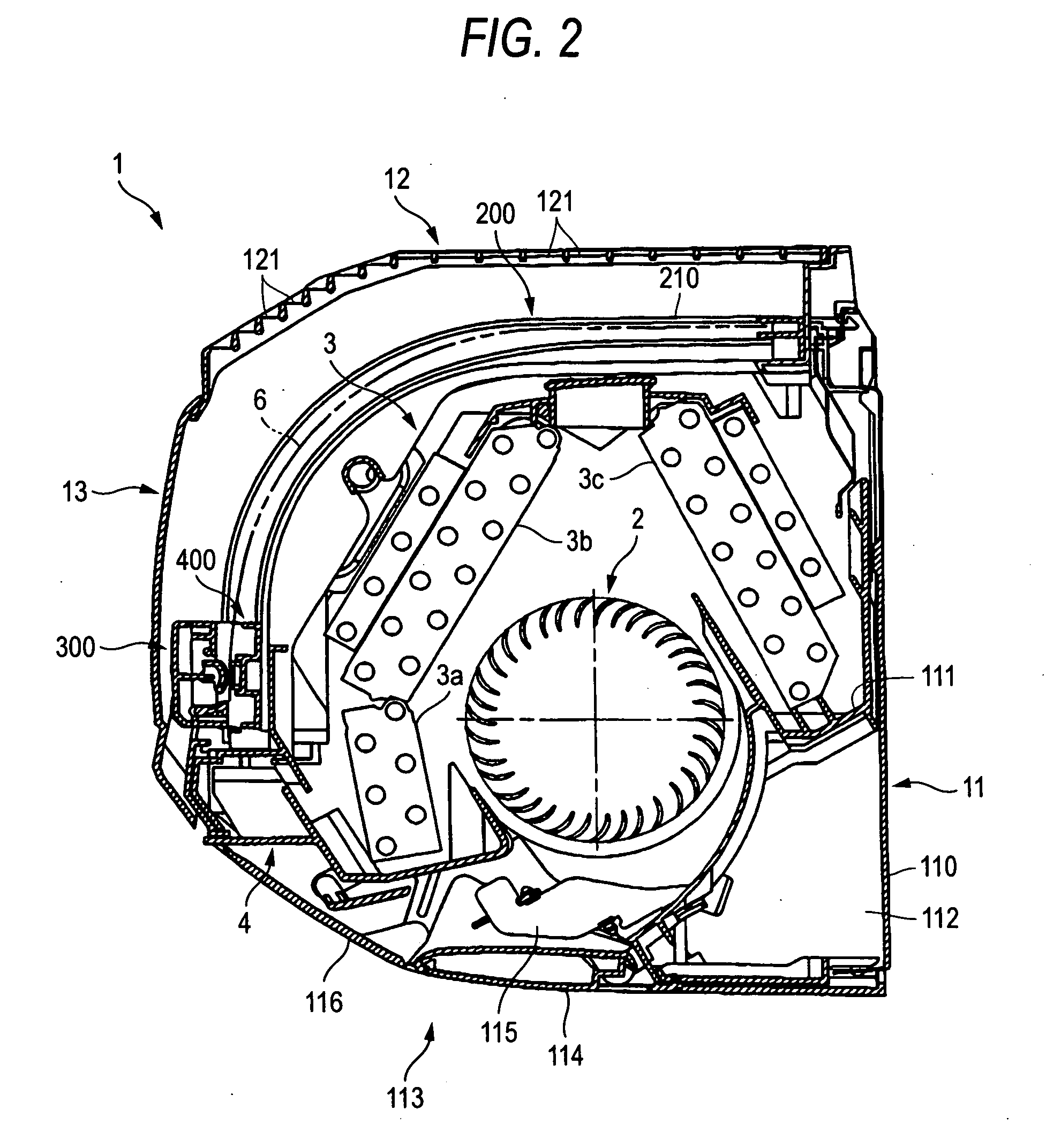
[0159] Now referring to the drawings, an explanation will be given of an embodiment of this invention. FIG. 1 is an exploded perspective view of an air conditioner according to an embodiment of this invention. FIG. 2 is a longitudinal sectional view of the air conditioner.

[0160] As seen from FIGS. 1 and 2, a body cabinet 1 of this air conditioner includes a back plate 110 attached onto a wall through an attaching screw (not shown), a base 11, an upper panel 12, a front panel 13, a right side panel 14 and a left side panel 15. All these members are molded problowers of synthetic resin. The body cabinet incorporates a cross-flow fan 2 serving as a blower fan, a heat exchanger 3, a drain pan 4, etc.

[0161] The base 11 is attached to the back plate 110 by a pair of right and left side plates (not shown) formed to overhang toward the wall from both sides of the heat exchanger 3. Between the side plates, the cross-flow fan 2 and heat exchanger 3 are supported. In this e...

second embodiment

(Second Embodiment)

[0233] Further, FIG. 18 is a perspective view of a second embodiment of an air conditioner according to this invention. FIG. 19 is a view for explaining the second embodiment of this invention; FIG. 19A is a first sectional view thereof, and FIG. 19B is an enlarged view of the main part thereof. FIG. 20 is a second sectional view of the second embodiment of the air conditioner according to this invention. FIG. 21 is a third sectional view of the second embodiment of the air conditioner according to this invention. FIG. 22 is a view for explaining a third embodiment of an air conditioner according to this invention; FIG. 22A is a first sectional view thereof, and FIG. 22B is an enlarged view of the main part thereof. FIG. 23 is a second sectional view of the third embodiment of the air conditioner according to this invention. FIG. 24 is a third sectional view of the third embodiment of the air conditioner according to this invention. FIG. 25 is a view for explainin...

third embodiment

(Third Embodiment)

[0251] Now referring to FIGS. 8 and 22 to 25, as the third embodiment, an explanation will be given of the configuration and operation in which the top panel 1001b is forcibly outwardly opened in contact with the dedusting device 1007.

[0252] The dedusting device 1007, as seen from FIG. 22A as a first state, is constructed with a dimension A from the air filter 1004 to the outer face of the case of the dedusting device 1007. The dedusting device 1007 is accommodated within a range of dimension B from the opposite air filter 1004 to the front panel 1001a, opposite to the lower end of the front face of the air filter 1004 in a relationship of “dimension A<dimension B”.

[0253] The top panel 1001b is adapted so that it can be translated vertically by a linkage mechanism 1010 provided on both sides of the top panel 1001b so that the dedusting device is not brought into contact therewith.

[0254] Further, the top panel 1001b is mounted on the upper part of the air conditi...


PUM

PropertyMeasurementUnit
Angleaaaaaaaaaa

Abstract

In an air conditioner having a main body provided with a panel 1 including a front panel 1a and a top panel 1b, the main body incorporating an air passage connecting an air inlet 2 and an air outlet 3, an air filter 4, a heat exchanger 5, a blower fan 6, and a dedusting device 7 attached to the front face of the air filter 4 which is reciprocated along the surface of the air filter 4, the top panel 1b is opened / closed as the dedusting device 7 is reciprocated.

Description

BACKGROUND OF THE INVENTION [0001] 1. Technical Field [0002] This invention relates to an indoor unit of an air conditioner, and more specifically to an air conditioner having a cleaning function of automatically removing dust deposited to a filter attached for dedusting. [0003] Further, this invention relates to an air conditioner provided with a dedusting device which is reciprocated along the surface of an air filter, and more particularly to an air conditioner capable of miniaturizing its body by reducing the space for operating the dedusting device. [0004] Further, this invention relates to an air conditioner, and more specifically to the structure of an air conditioner provided with a filter take-off preventing unit for exactly holding an air filter so that the air filter attached for dedusting is not taken off from a filter rail. [0005] 2. Related Art [0006] The air conditioner (indoor unit) is provided with a filter for dedusting for preventing dust from flowing into the uni...

Claims


Application Information

Patent Timeline
IPC IPC(8): B01L1/04F24F1/00F24F8/108F24F8/90
CPCB01D46/0065B01D46/42B01D2279/50F24F2003/1639F24F3/1603F24F13/28F24F2001/0048F24F1/0007F24F1/0057F24F8/90F24F1/0073F24F1/0063B01D46/681F24F8/108
Inventor SHIBUYA, MAKOTOUMENAKA, HIDEYUKINAGASHIMA, TSUTOMUSUGIYAMA, SHINNJIKONDO, RYOUHEIODA, MASATOTAKAHASHI, TOMOMI
Owner FUJITSU GENERAL LTD
Features
  • Generate Ideas
  • Intellectual Property
  • Life Sciences
  • Materials
  • Tech Scout
  • Unparalleled Data Quality
  • Higher Quality Content
  • 60% Fewer Hallucinations
Learn More