Cracked barrel detection system

a detection system and barrel technology, applied in the direction of manufacturing tools, metal working devices, shape safety devices, etc., can solve the problems of difficult identification of crack defects, cracks formed along relatively unsupported lengths during the stamping process, and elongated tubular parts are susceptible to cracking, so as to ensure the effect of not adversely affecting the manufacturing process

Inactive Publication Date: 2007-03-22
ILLINOIS TOOL WORKS INC
View PDF17 Cites 0 Cited by
  • Summary
  • Abstract
  • Description
  • Claims
  • Application Information

AI Technical Summary

Benefits of technology

[0011] An advantage of the present invention is providing a device that can identify cracked components so that the cracked component can be discarded.
[0012] Another advantage of the present invention is providing a device for identifying cracked components in which crack defects appear along the extended lengths of hollow components such as tubes, pipes or the like.
[0013] Still another advantage of the present invention is providing a cracked component identifying system incorporated directly with a press performing a stamping process, so that a flawed part can be identified immediately and quickly.
[0014] Still another advantage of the present invention is providing a crack detecting system for tubes that operates in conjunction with a press, such as a flaring press, for performing other functions so that no additional time is required for testing the tubular body and the manufacturing process is not adversely impacted.
[0015] Other features and advantages of the invention will become apparent to those skilled in the art upon review of the following detailed description, claims and drawings in which like numerals are used to designate like features.

Problems solved by technology

Elongated tubular parts can be susceptible to cracking during stamping processes.
Force applied against hollow, elongated parts such as tubes or the like when forming flanges or flares is substantially axial, and can cause cracks to form along relatively unsupported lengths during the stamping process.
It is often difficult to identify such crack defects.
Cameras and visual inspections are often inadequate.
Even a hairline crack can be significant in detrimentally affecting the final strength of the part.
Compression limiters and the like can fail if a small crack in the barrel thereof is allowed to propagate, thereby weakening the axial strength of the finished part.

Method used


Image

  • Cracked barrel detection system
  • Cracked barrel detection system
  • Cracked barrel detection system

Examples


Embodiment Construction

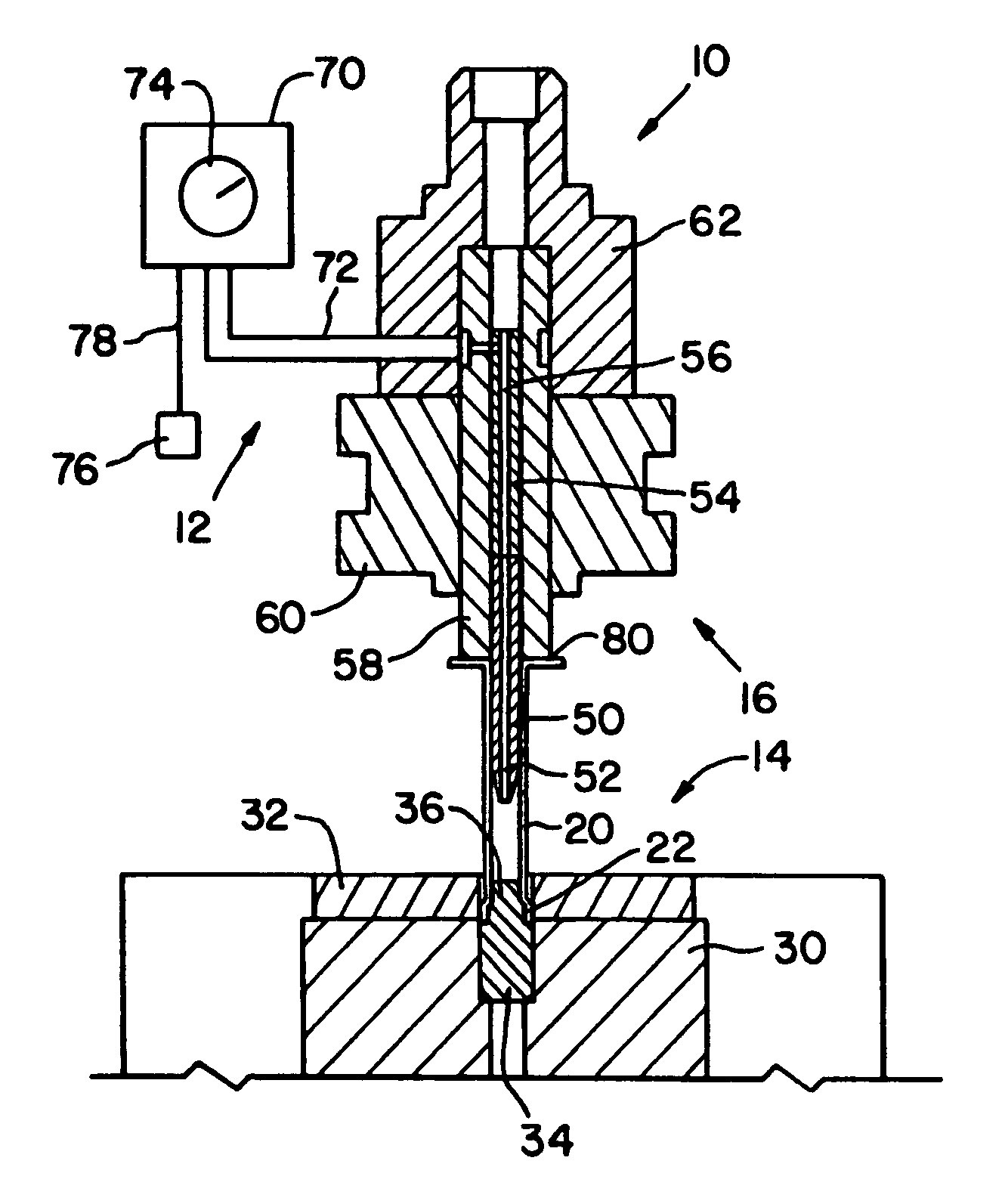
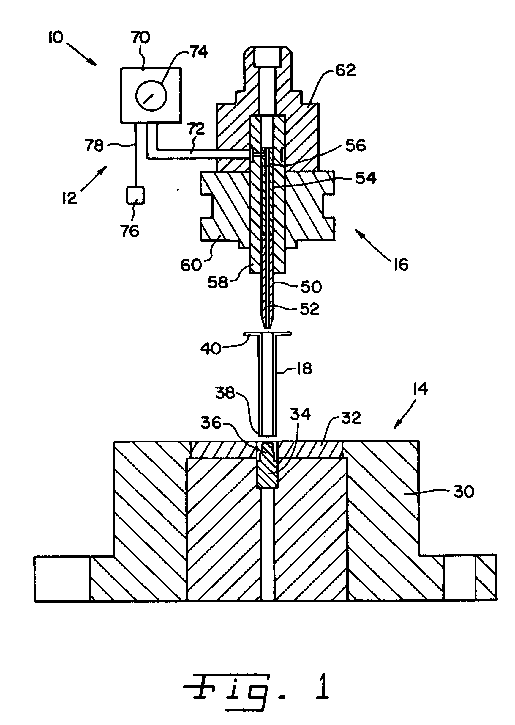
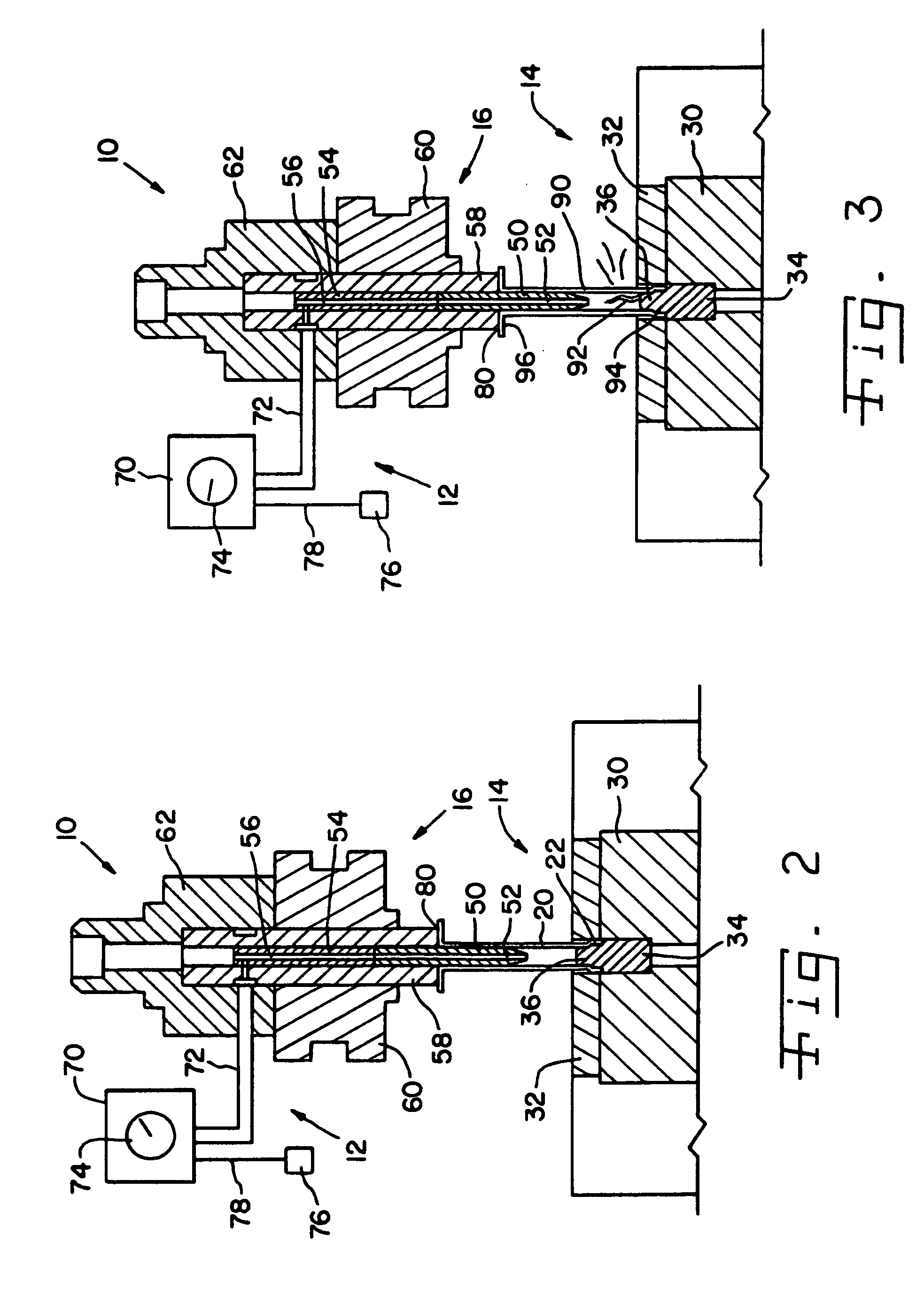
[0021] Referring now more specifically to the drawings and to FIG. 1 in particular, a punch press assembly 10 is shown. Punch press assembly 10 includes a crack test system 12 in accordance with the present invention which works in conjunction with a die block assembly 14 and a punch chuck assembly 16 and of press assembly 10. Punch press assembly 10 in the exemplary embodiment is shown as a flaring press for forming a flare on the end of a pre-formed part 18 to complete a finished part 20 having a flare 22 on the end thereof (FIG. 2). It should be understood that the configuration of pre-formed part 18 and finished part 20 are exemplary in nature and should not be considered as limiting of the present invention. The concepts of the present invention can be used to form other types of parts, different from those shown in the example.

[0022] While FIG. 1 is shown and described to have pre-form part 18, and FIG. 20 is shown and described to have completed part 20, it should be underst...


PUM

PropertyMeasurementUnit
pressureaaaaaaaaaa
shapeaaaaaaaaaa
shapesaaaaaaaaaa

Abstract

A crack test includes flowing pressurized fluid to a generally tubular part in a flare stamping process. As the flare is completed the part is sealed on opposite ends and pressurization of the inside of the part is used to determine integrity of the part.

Description

FIELD OF THE INVENTION [0001] The present invention relates generally to stamped parts and components and, more particularly, the invention pertains to test systems and procedures for identifying cylindrical parts with cracks therein. BACKGROUND OF THE INVENTION [0002] Stampings and progressive stampings are used to manufacture parts and pieces of many different types and shapes for use in a variety of different assemblies and constructions. Metal can be shaped into many different forms and configurations by the application of force causing a metal blank to conform to the shape of a die used while applying the force. Simple parts and pieces can be made by a single stamping. In a single stamping, force is applied in a single event so that the metal conforms to a die used while applying the force. For more complex parts or parts taking a shape quite different from the original metal blank, progressive stampings are used. In progressive stampings, a series of dies are used in a series ...

Claims


Application Information

Patent Timeline
Patent Type & Authority Applications(United States)
IPC IPC(8): B21J5/00
CPCB21D41/02
Inventor HEAVENS, GLENN G.
Owner ILLINOIS TOOL WORKS INC
Why Eureka
Try Eureka