Method of pacing and disconnecting transfers on a source strobed bus

a computer system and bus technology, applied in the field of computer systems, can solve the problems of severe affecting system performance, inability to act, and disconnecting the receiving device from the source, and achieve the effect of efficient and timely manner, and not adversely affecting system performan

Inactive Publication Date: 2005-06-21
MICRON TECH INC
View PDF17 Cites 10 Cited by
  • Summary
  • Abstract
  • Description
  • Claims
  • Application Information

AI Technical Summary

Benefits of technology

[0008]The invention provides a mechanism to disconnect transfers on a source strobe bus in an efficient and timely manner so that system performance is not adversely impacted when a receiving device cannot accept a data transfer.
[0009]The invention also provides a mechanism to pace transfers on a source strobe bus in an efficient and timely manner so that system performance is not adversely impacted when a data transfer must be stalled.
[0010]The above and other features and advantages are achieved by a hub based computer system having a central hub that communicates with a plurality of satellite devices over respective link buses. Each link bus is substantially the same and adheres to a predefined link bus protocol. The satellite devices are also connected to industry standard buses / devices. All components within the system are capable of communicating with each other through the hub. Each link bus includes a status line that allows each device connected to the same link bus to accept, deny, or delay a data transfer on the link bus. If accepted, the same status line can be used by the transferor and target of a data transfer, if necessary, to stall or pace the transfer as needed. The link bus protocol establishes a window in which the status line may convey data transfer disconnecting or pacing status information. The protocol further includes a method of transferring, retrying, or aborting data transfers based on the disconnecting status information in an efficient and timely manner.

Problems solved by technology

There will be times, however, when the device connected to the additional bus is unable to accept a data transfer from the source strobe bus.
In addition, there may be times when the receiving device has become disconnected from the source strobed bus or is otherwise incapable of acting on the transfer due to a power-down or other condition.
Unnecessary delays, erroneous data processing and deadlocking conditions would severely impact system performance.
As such, there will be times when the receiving device is incapable of completing a data transfer.
This may arise, for example, when the input buffers of the receiving device become full and are no longer capable of receiving more data.
If this happens, data transferred to the receiving device will be dropped, which may lead to erroneous processing or deadlock conditions within the system.
Other times, the receiving device may not have an outlet for the data (i.e., the device / bus the receiving device is connected to cannot accept data due to e.g., a bottleneck condition).

Method used


Image

  • Method of pacing and disconnecting transfers on a source strobed bus
  • Method of pacing and disconnecting transfers on a source strobed bus
  • Method of pacing and disconnecting transfers on a source strobed bus

Examples


Embodiment Construction

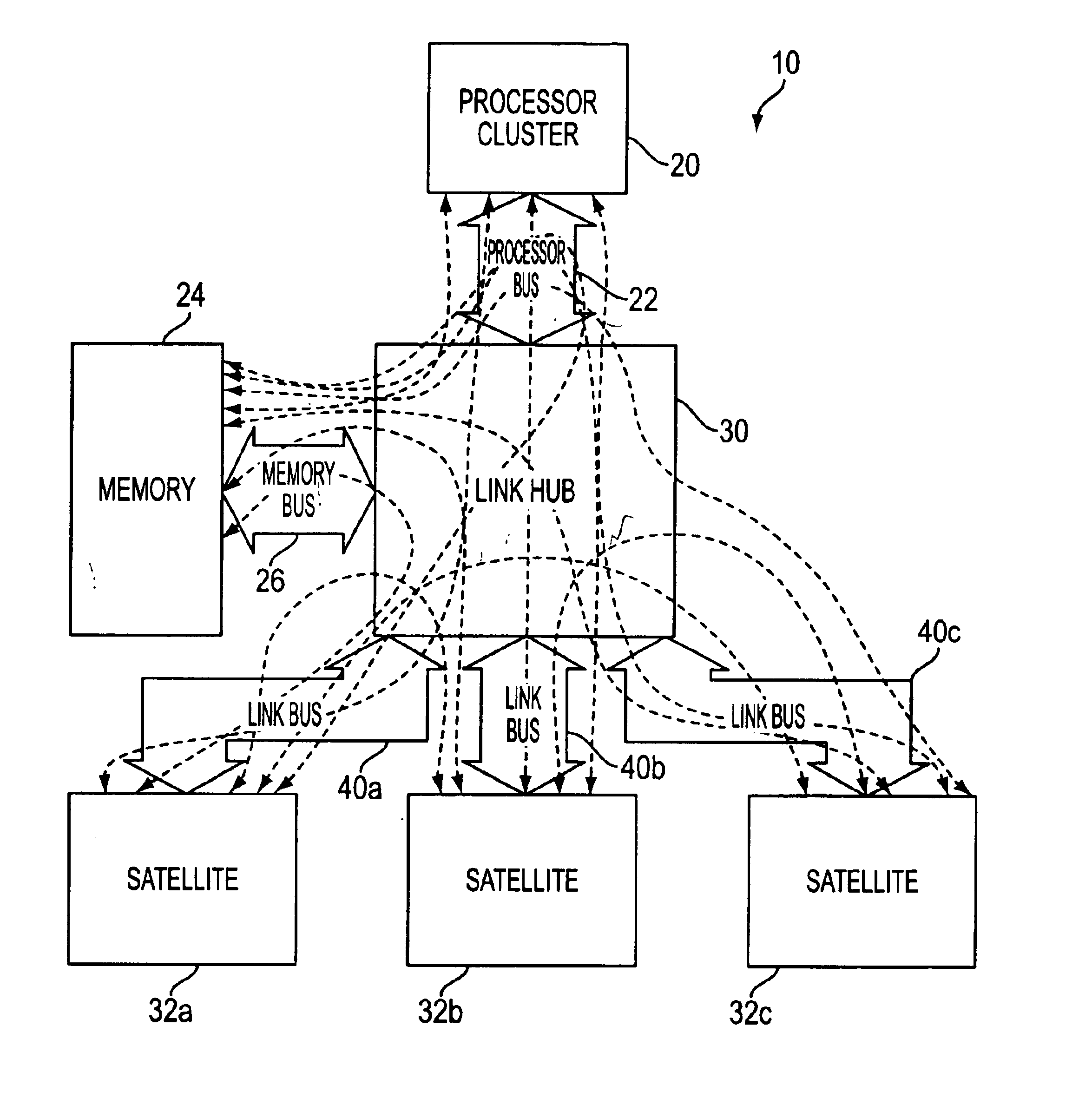
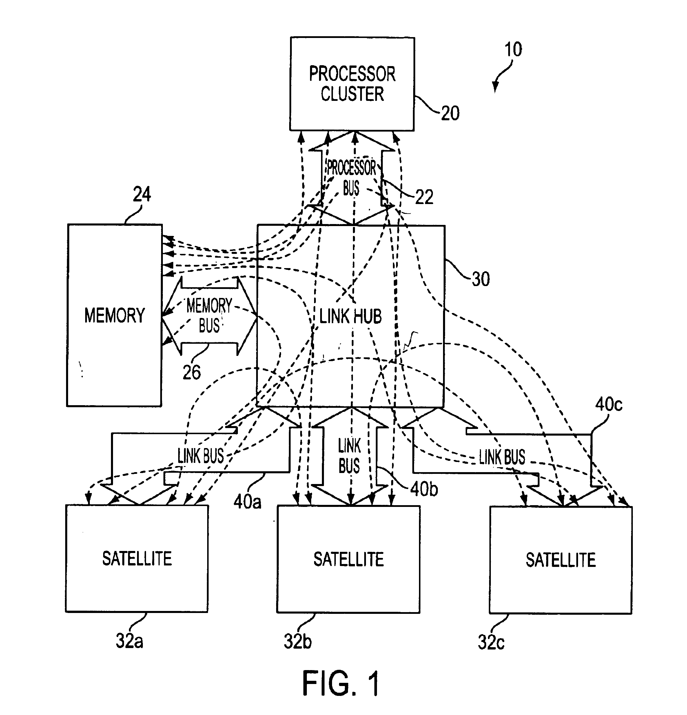
[0017]FIG. 1 is a hub based computer system 10 utilizing link buses 40a, 40b, 40c (collectively referred to herein as “link buses 40”) in accordance with an exemplary embodiment of the invention. The system 10 includes a processor cluster 20, a memory device 24, a link hub 30 and a plurality of satellite devices 32a, 32b, 32c (collectively referred to herein as “satellite devices 32”). The processor cluster 20 may contain one or many processor units. Although not required to practice the invention, if more than one processing unit is contained within the cluster 20, they are preferably identical to each other. The satellite devices 32 can be bridges or hubs to industry standard buses, such as e.g., PCI, PCI-X and AGP, or the devices 32 can be other components typically found in a computer system. The devices 32 can be connected to one or more I / O devices if so desired.

[0018]The link hub 30 is connected to the processor cluster 20 by a dedicated processor bus 22. The link hub 30 is c...


PUM


Abstract

A hub based computer system having a central hub that communicates with a plurality of satellite devices over respective link buses. Each link bus is substantially the same and adheres to a predefined link bus protocol. The satellite devices are also connected to industry standard buses/devices. All components within the system are capable of communicating with each other through the hub. Each link bus includes a status line that allows each device connected to the same link bus to accept, deny, or delay a data transfer on the link bus. If accepted, the same status line can be used by the transferor and target of a data transfer, if necessary, to stall or pace the transfer as needed. The link bus protocol establishes a window in which the status line may convey data transfer disconnecting or pacing status information. The protocol further includes a method of retrying or aborting transfers based on the disconnecting status information.

Description

FIELD OF THE INVENTION[0001]The invention relates to computer systems, and more particularly to a method of pacing and disconnecting transfers on a source strobed computer system bus.BACKGROUND OF THE INVENTION[0002]Several of today's computer system architectures employ a source strobed bus and method to transfer data between devices. In a typical source strobe architecture, the transmitting device transmits to the receiving device a clock signal / strobe and data. The strobe alerts the receiving device that valid data has been transmitted over the bus. Computer bus architectures such as AGP (accelerated graphics port), DDR SDRAM (double data rate synchronous dynamic random access memory), and RDRAM (Rambus random access memory) utilize source strobes in this manner.[0003]A source strobe data bus is an efficient mechanism for transferring large amounts of data on a minimum number of pins or connections between devices. Often times at least one of the devices connected to the source s...

Claims


Application Information

Patent Timeline
Patent Type & Authority Patents(United States)
IPC IPC(8): G06F13/40
CPCG06F13/4036G06F13/4022
Inventor PORTERFIELD, A. KENT
Owner MICRON TECH INC
Why Eureka
Try Eureka