Apparatus and method for adjusting the resonant frequency of an oscillating device

a technology of oscillating device and resonant frequency, which is applied in the direction of optics, instruments, optics, etc., can solve the problems of high voltage requirements, inability to precisely set the resonant frequency of such an oscillating device by manufacturing methods, and unusual mechanical gain of the initial drive torsional hinged resonant device made of silicon, etc., to achieve the effect of reducing stiffness, reducing stiffness, and reducing the cross-sectional area of the connecting region

Active Publication Date: 2007-03-22
TEXAS INSTR INC
View PDF2 Cites 18 Cited by
  • Summary
  • Abstract
  • Description
  • Claims
  • Application Information

AI Technical Summary

Benefits of technology

[0007] These and other problems are generally solved or circumvented and technical advantages are generally achieved by embodiments of the present invention, which provides a torsional hinged anchor or mounting structure such as a mirror that is power efficient. The structure comprises a pair of torsional hinges that support a resonant member or device such as a mirror that oscillates around a pivot axis. Each hinge of the pair of torsional have a first end connected to the resonant device or mirror, and a second end connected one each to a first or second anchor member (i.e., first and second). The first and second anchor members each have a selected thickness and include a central portion that is connected to a respective torsional hinge and also include at least one mounting portion that is attached to a support structure. The central portion and the mounting portions are joined by a connecting region having a reduced stiffness. The reduced stiffness may be achieved by reducing the cross-sectional area of the connecting region. According to one embodiment, the connecting region compresses a thinned area or trench. The resonant frequency of the device can be increased to a selected value, by applying a material such as solder or a UV curable adhesive over the thermal areas to stiffen the connection between the torsional hinges and the oscillating member. According to a preferred embodiment, the resonant device is made of silicon.

Problems solved by technology

However, every new technology has its own set of problems and resonant torsional hinged devices, such as mirrors, are no exception.
As an example, inertially driven torsional hinged resonant devices made of silicon exhibit unusually high mechanical gain.
For battery powered applications, such high voltage requirements are a problem.
As will also be appreciated, the resonant frequency of such an oscillating device cannot be precisely set by manufacturing methods.

Method used


Image

  • Apparatus and method for adjusting the resonant frequency of an oscillating device
  • Apparatus and method for adjusting the resonant frequency of an oscillating device
  • Apparatus and method for adjusting the resonant frequency of an oscillating device

Examples


Embodiment Construction

[0014] The making and using of the presently preferred embodiments are discussed in detail below. It should be appreciated, however, that the present invention provides many applicable inventive concepts that can be embodied in a wide variety of specific contexts. The specific embodiments discussed are merely illustrative of specific ways to make and use the invention, and do not limit the scope of the invention.

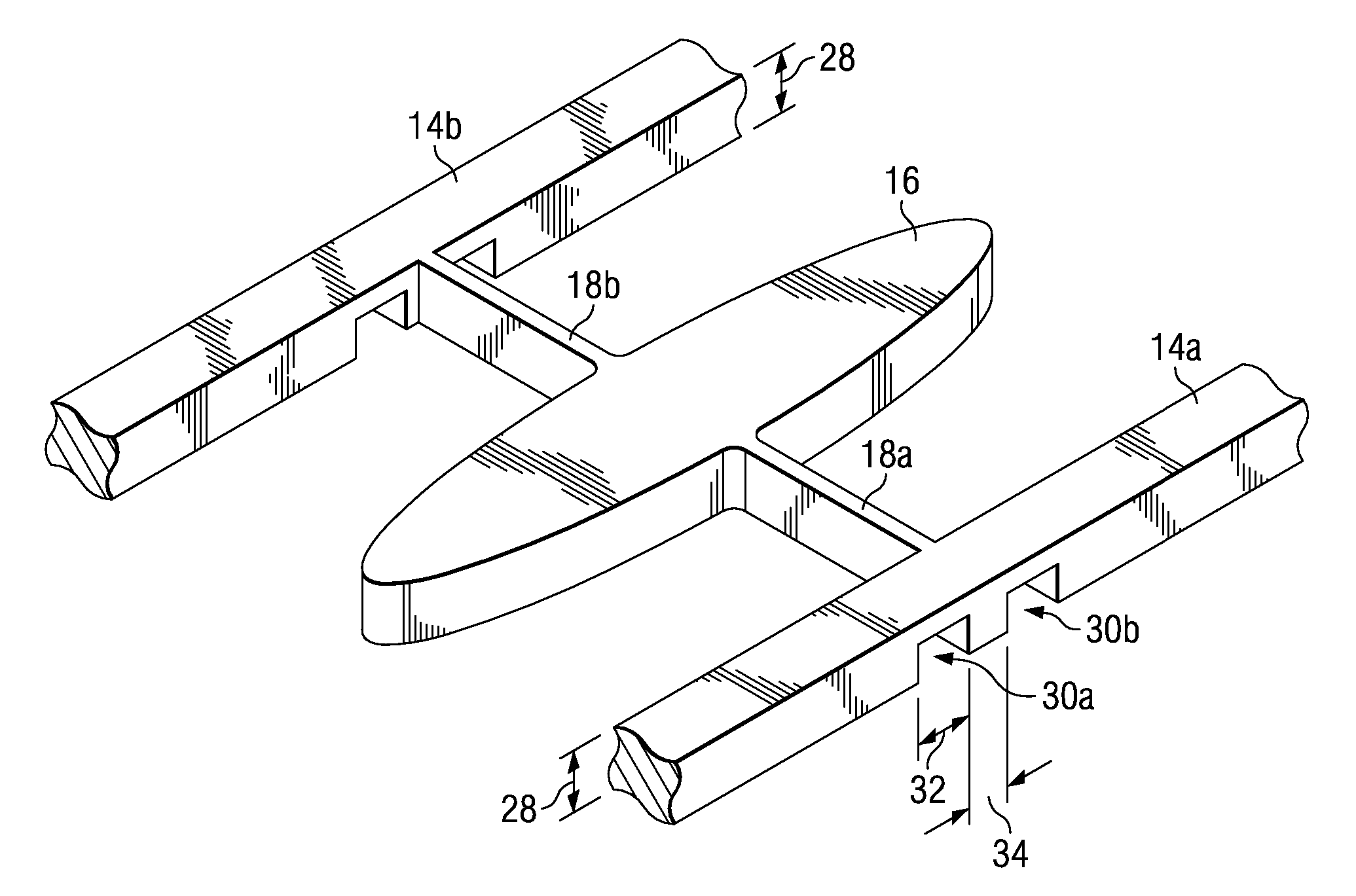
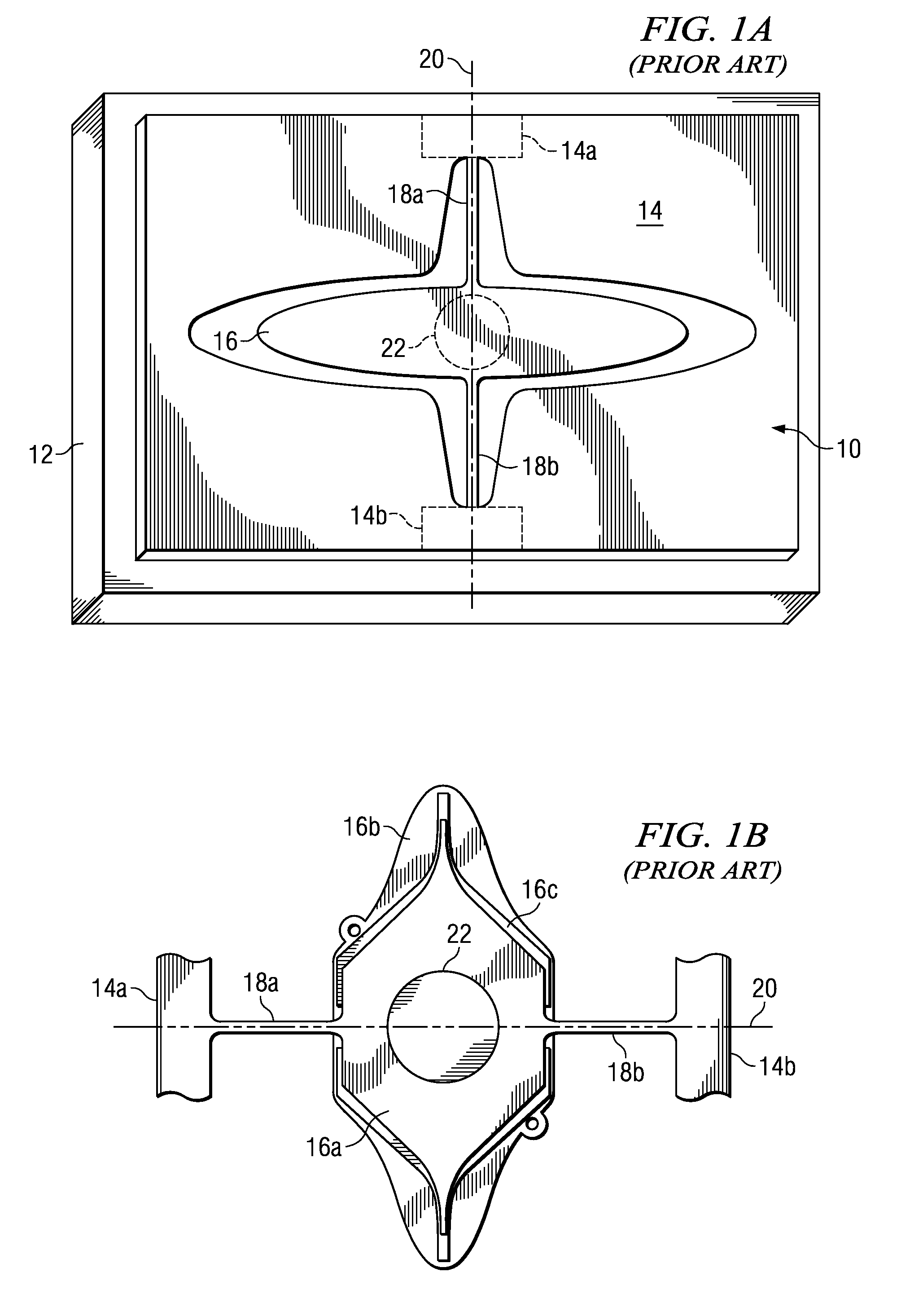
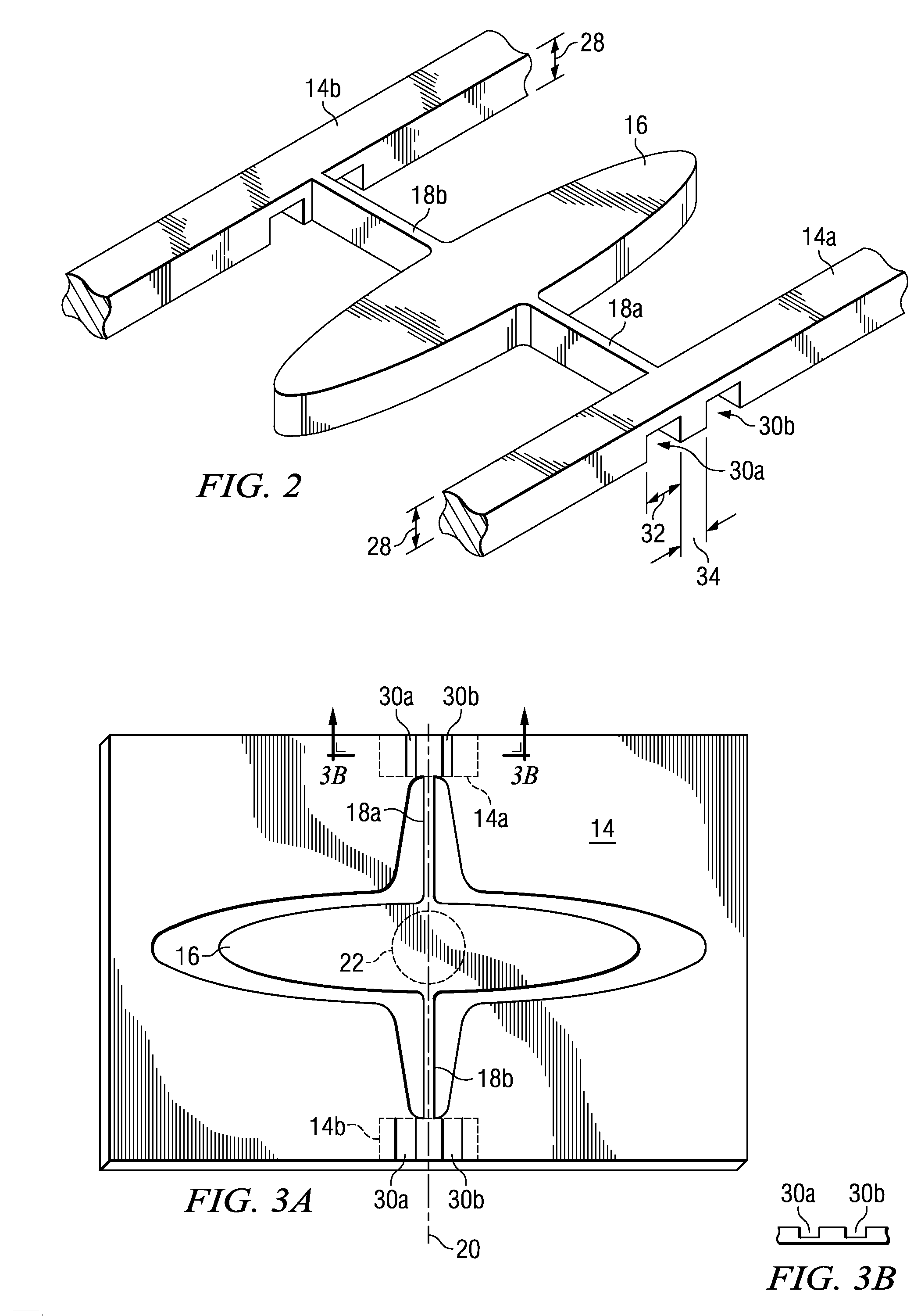
[0015] Referring now to FIGS. 1A and 1B, the two types of prior art torsional hinged mirrors will be discussed. The selected and illustrated mirrors are examples only and are in no way intended as limitations on the types of torsional hinged mirrors may advantageously benefit from the present invention. FIG. 1A is a single axis single layer mirror device 10 and includes a structure 12 that supports a frame member 14. An operating surface such as reflecting or mirror surface 16 is in turn supported by a single pair of torsional hinges 18a and 18b that lie along pivoting axis...


PUM


Abstract

A method for increasing the resonant frequency of a torsional hinged device having a reduced attaching area between the torsional hinges and the supporting anchors. The resonant frequency is increased by adding a material over the reduced area to stiffen the connection between the torsional hinges and the support anchors.

Description

CROSS-REFERENCE TO RELATED APPLICATIONS [0001] This application relates to the following co-pending and commonly assigned patent applications: (TI-60301) Ser. No. ______, filed herewith, entitled Resonant Oscillating Device Actuator Structure and (TI-60322) Ser. No. ______, filed herewith, entitled Magnet On Frame Oscillating Device, which applications are hereby incorporated herein by reference.TECHNICAL FIELD [0002] The present invention relates generally to the field of torsional hinged MEMS (Micro Electro Mechanical Systems) oscillating devices. More particularly, the invention relates to a method of adjusting the resonant frequency of such an oscillating device having a power efficient actuator structure for driving and maintaining oscillations of the torsional hinged device. BACKGROUND [0003] The use of rotating polygon scanning mirrors in laser printers to provide a beam sweep or scan of the image of a modulated light source across a photoresisted medium, such as a rotating d...

Claims


Application Information

Patent Timeline
Patent Type & Authority Applications(United States)
IPC IPC(8): G02B26/00
CPCG02B26/0858G02B26/085
Inventor DEWA, ANDREW STEVEN
Owner TEXAS INSTR INC
Why Eureka
Try Eureka