Razor assembly

a technology of razors and parts, applied in the direction of metal working devices, etc., can solve the problems of unsatisfactory aspects and the impracticality of shaving cream in a wet shaving environment, and achieve the effects of clutter and mess, ease of use and safety

Inactive Publication Date: 2007-03-29
EDGEWELL PERSONAL CARE BRANDS LLC
View PDF99 Cites 0 Cited by
  • Summary
  • Abstract
  • Description
  • Claims
  • Application Information

AI Technical Summary

Benefits of technology

[0011] An advantage of the present invention is the ease of use and safety provided by the positional self-adjustment of the shaving aid body and the razor cartridge provided by the present invention. The linkage of the present invention, and the self-adjusting movement it provides, enables the relative positions of the shaving aid body and the razor cartridge to be continuously adjusted so that a desirable orientation between the contact surface of the shaving aid body and the cutting edges of the razor blades within the razor cartridge can be maintained automatically during the shaving process. The linkage is connected directly or indirectly to the razor cartridge and to the shaving aid body in such a manner that movement of one of the razor cartridge or the shaving aid body in a first direction causes the other of the razor cartridge or the shaving aid body to move in a second direction substantially opposite the first direction. A change in the height of the shaving aid body (and therefore the position of the contact surface), for example, can be accommodated automatically relative to the position of the razor blades within the razor cartridge.
[0012] Another advantage of the present invention is that a shaving aid can be applied during the shaving process. As a result, the shaving aid within the shaving aid body can be successfully applied and utilized within a wet shaving environment. The need for an independent source of shaving cream or other shaving preparation, and the clutter and mess associated therewith, is consequently eliminated.

Problems solved by technology

Although shaving preparations desirably enhance the shaving process, they also have undesirable aspects.
For example, shaving cream is impractical in a wet shaving environment because the shaving cream is often washed away before the shaving process can be completed.

Method used


Image

  • Razor assembly
  • Razor assembly
  • Razor assembly

Examples


example i

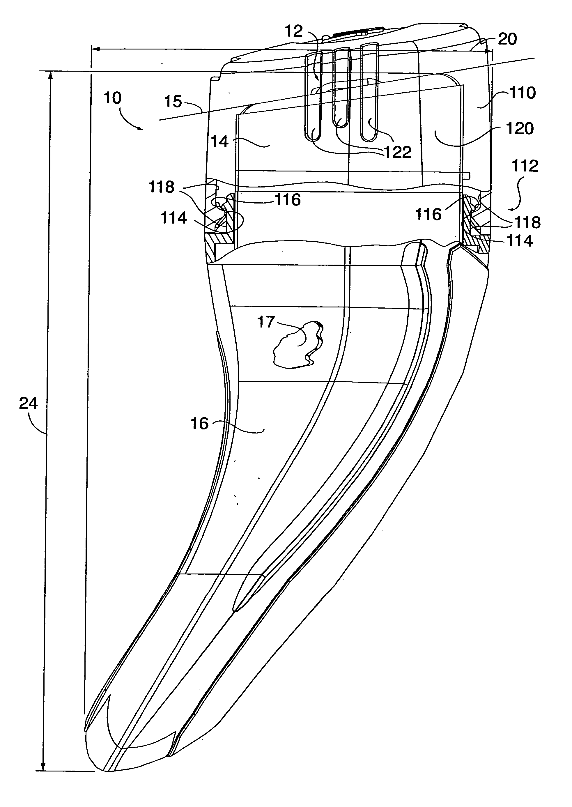
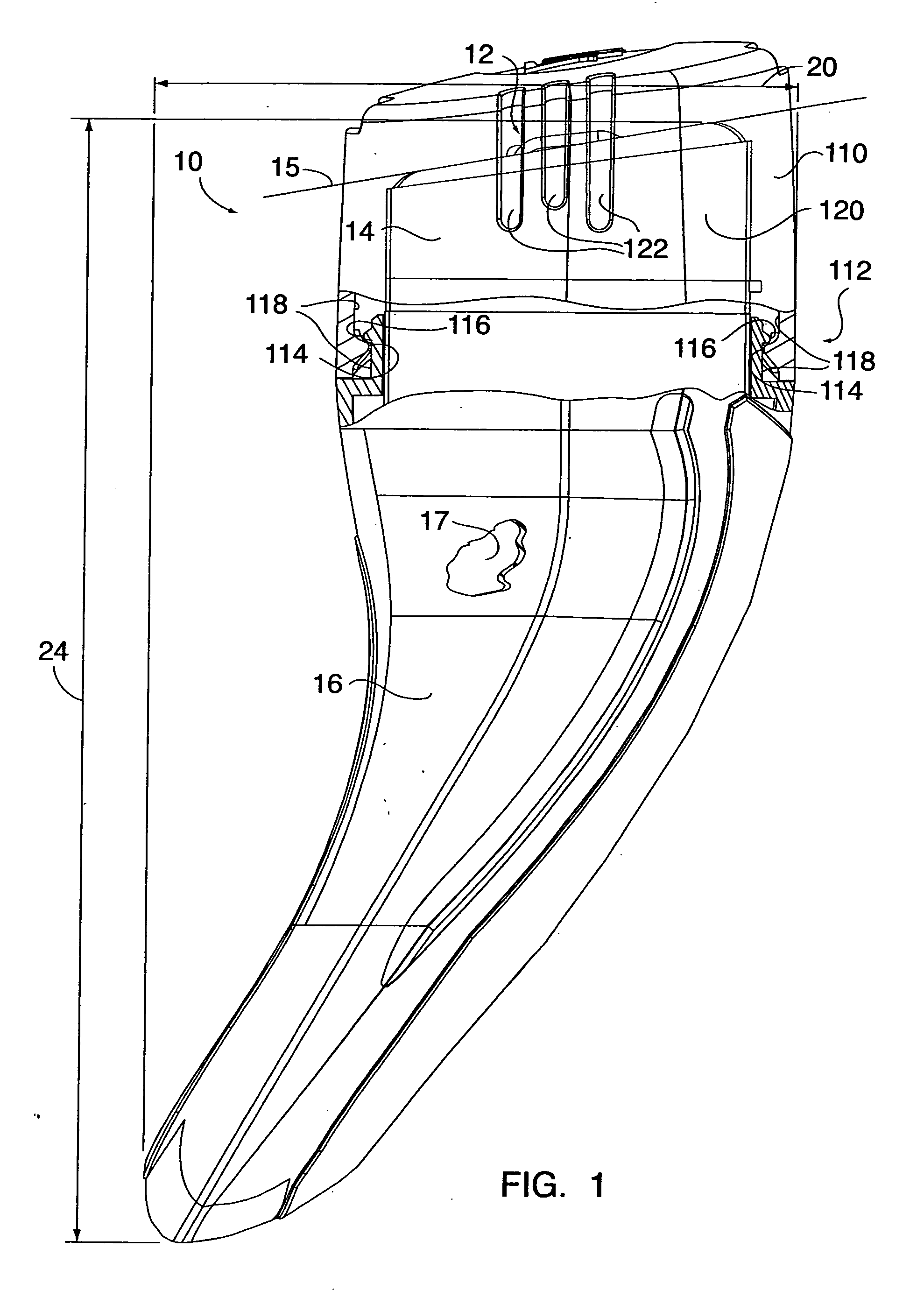
[0065] In an embodiment shown in FIGS. 1-8, a razor assembly 10 is provided that includes a razor cartridge 12, a shaving aid body 14, a handle 16, and a linkage 18 pivotally connected to the handle 16.

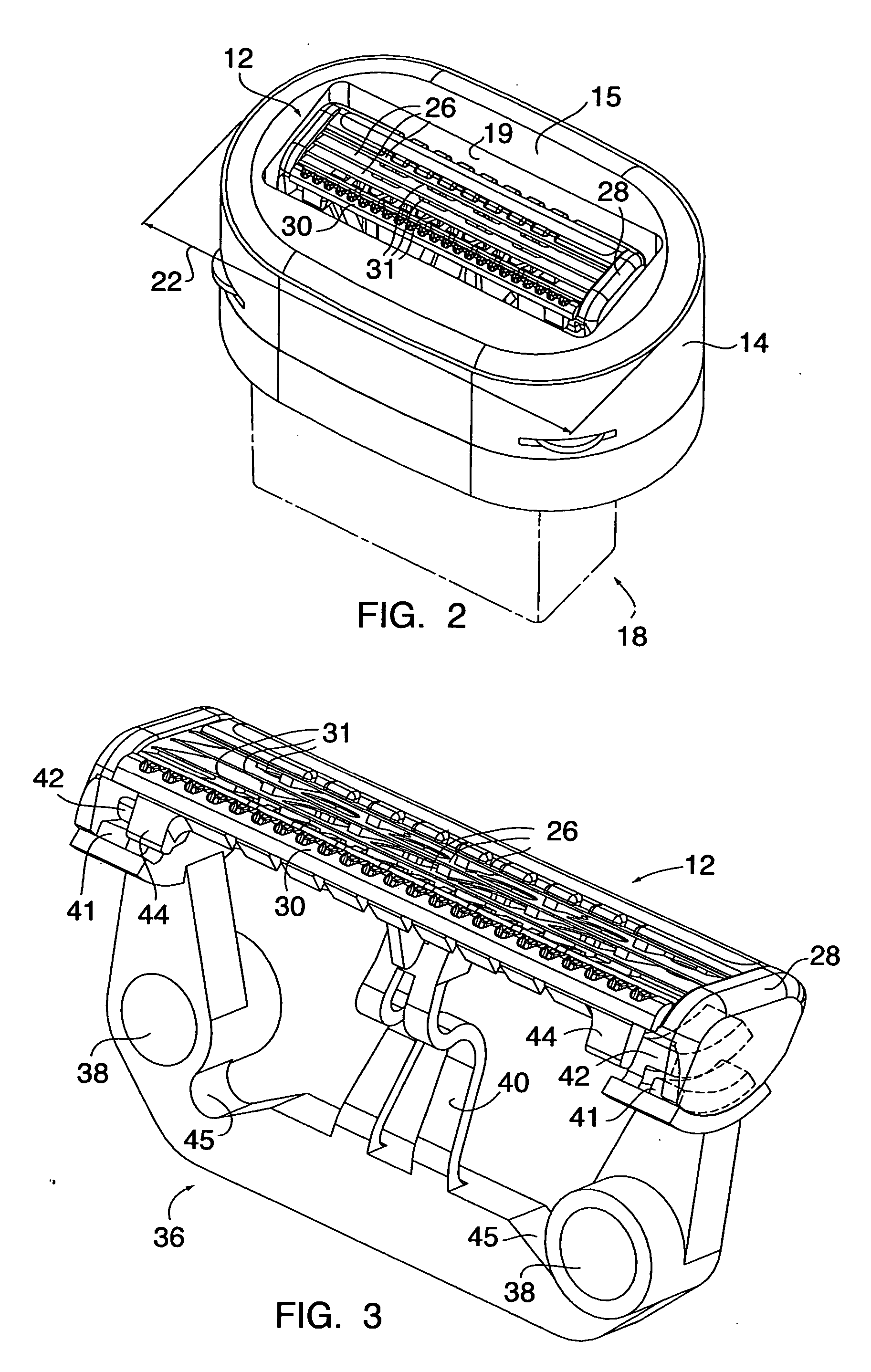
[0066] Referring to FIG. 3, the razor cartridge 12 includes a guard 30 and a plurality of razor blades 26 attached to a frame 28. The razor cartridge 12 is pivotally attached to a holder 36 at each lengthwise end of the cartridge 12. The holder 36 includes a pair of mounting apertures 38 and a cartridge-biasing member 40. The holder 36 and the razor cartridge 12 are pivotally attached to one another by mating pairs of arcuately shaped features 41,42 (e.g., tabs) at each lengthwise end. The arcuate shapes of the features 42,41 define the pivotal path of the razor cartridge 12 relative to the holder 36. Physical stops 44 are provided to limit pivotal movement between the razor cartridge 12 and the holder 36. The cartridge-biasing member 40 extends out from the holder 36 and biases the ...

example ii

[0074] In an embodiment shown in FIGS. 1, 2, and 9-22, a razor assembly 10 is provided that includes a razor cartridge 12, a holder 78, a shaving aid body 14, a base 80, a handle 16, and a linkage 18 pivotally connected to the handle 16.

[0075] Referring to FIGS. 2, 9-13, 15 and 16, the razor cartridge 12 includes a guard 30 and a plurality of razor blades 26 attached to a frame 28. The razor cartridge 12 is pivotally attached to the holder 78 at each lengthwise end of the cartridge. The holder (see FIG. 13) includes a plurality of guide panels 84, a pair of assembly apertures 86, and a cartridge-biasing member 88. In the embodiment shown in FIGS. 10-13, the holder 78 and the razor cartridge 12 are pivotally attached to one another by mating pairs of arcuately shaped features 90,91 (e.g., tabs) at each lengthwise end. The arcuate shape of the features 91,90 defines the pivotal path of the razor cartridge 12 relative to the holder 78. Other schemes for pivotally attaching the razor c...

example iii

[0086] In an embodiment shown in FIGS. 23 and 24, a razor assembly 10 similar to that described above in Example II is shown having a different linkage. In this embodiment, the linkage 18 includes a linkage member 190, a shaving aid body carriage 138 (“SAB carriage”), and a razor cartridge carriage 140 (“RC carriage”). The linkage member 190 hereinafter referred to as a pivot link 190, includes at least one lengthwise-extending handle pivot axle 142, and a pair of pivot rollers 192.

[0087] The SAB carriage 138 is similar to that described in Example II except that it includes a pair of roller rails 194 in place of seats 156. The RC carriage 140 is also similar to that described in Example II except that it includes a pair of roller rails 196 in place of seats 160.

[0088] The pivot rollers 192 of the pivot link 190 and the roller rails 194,196 of the SAB carriage 138 and RC carriage 140 have complimentary features that function in the manner described below. For example, the pivot ro...


PUM


Abstract

A razor assembly is provided that includes a razor cartridge with one or more razor blades, a shaving aid body, a handle, and a linkage pivotally connected to the handle. The linkage is connected to the razor cartridge and the shaving aid body in a manner such that the razor cartridge and the shaving aid body are moveable relative to the handle. Movement of one of the razor cartridge or the shaving aid body in a first direction causes the other of the razor cartridge or the shaving aid body to move in a second direction substantially opposite the first direction. As a result, the positions of the shaving aid body and the razor cartridge are continuously adjusted to maintain the contact surface of the shaving aid body approximately co-planar with the cutting edges of the razor blades within the razor cartridge.

Description

CROSS REFERENCE TO RELATED APPLICATIONS [0001] This application is a division of U.S. patent application Ser. No. 10 / 367,255 filed Feb. 14, 2003, which claims the benefit of Provisional Patent application Ser. No. 60 / 375,844, filed Apr. 24, 2002 and Provisional Patent application Ser. No. 60 / 405,185 filed Aug. 21, 2002.BACKGROUND OF THE INVENTION [0002] 1. Technical Field [0003] This invention relates to shaving devices in general, and to shaving devices that include a shaving aid in addition to one or more razor blades in particular, and replacement cartridges operable therewith. [0004] 2. Background Information [0005] Modern safety razors include a plurality of razor blades disposed within a cartridge that is pivotally or rigidly mounted on a handle. Each of the razor blades has a cutting edge that is contiguous with a shave plane. Some safety razors (also referred to hereinafter as razor assemblies) have a disposable cartridge for use with a reusable handle, while others have a h...

Claims


Application Information

Patent Timeline
Patent Type & Authority Applications(United States)
IPC IPC(8): B26B21/52B26B21/14B26B21/22B26B21/40B26B21/44
CPCB26B21/222B26B21/44B26B21/4062B26B21/4037
Inventor COFFIN, DAVID C.
Owner EDGEWELL PERSONAL CARE BRANDS LLC
Why Eureka
Try Eureka