Sampler for engine exhaust dilution

a technology of engine exhaust and sampler, which is applied in the field of sampler, can solve the problems of large size, inability to carry, and high cost of cvs, and achieve the effects of reducing the number of sample samples

Inactive Publication Date: 2007-03-29
HORIBA LTD
View PDF14 Cites 18 Cited by
  • Summary
  • Abstract
  • Description
  • Claims
  • Application Information

AI Technical Summary

Benefits of technology

[0012] It is an object of the invention to provide an improved sampler for engine exhaust dilution that provides accurate sample flow measurements over a wide range of dilution ratios and sample ratios. An improved system of the invention provides accurate dilution for engine exhaust PM measurement based on number and mass. In preferred implementations, the sampler may be used on any size engine or vehicle, and is suitable for steady-state and transient tests. Further, an improved partial flow sampling system of the invention may be portable, and relatively inexpensive when compared to a full flow dilution system.

Problems solved by technology

However, the CVS is expensive, large in size, and not portable.
Due to the nature of the dilution process, a complicated control system must be integrated for proportional control during transient testing conditions.
Accordingly, significant errors in the sample flow may be generated when the sample flow is small, in other words, when the dilution ratio is high or the sample ratio is low.
In this way, small errors in total flow and dilution air flow may result in large errors in the sample flow.
Based on the working principle of the conventional partial flow sampling system, the conventional partial flow sampling system cannot avoid significant errors on the sample flow rate under some conditions.

Method used


Image

  • Sampler for engine exhaust dilution
  • Sampler for engine exhaust dilution
  • Sampler for engine exhaust dilution

Examples


Embodiment Construction

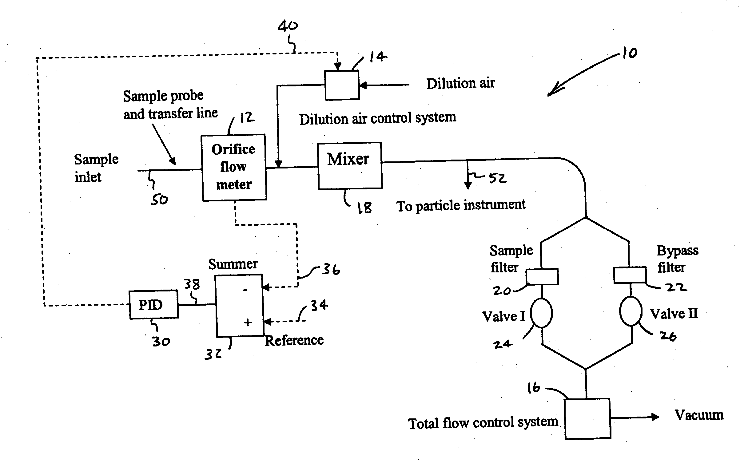
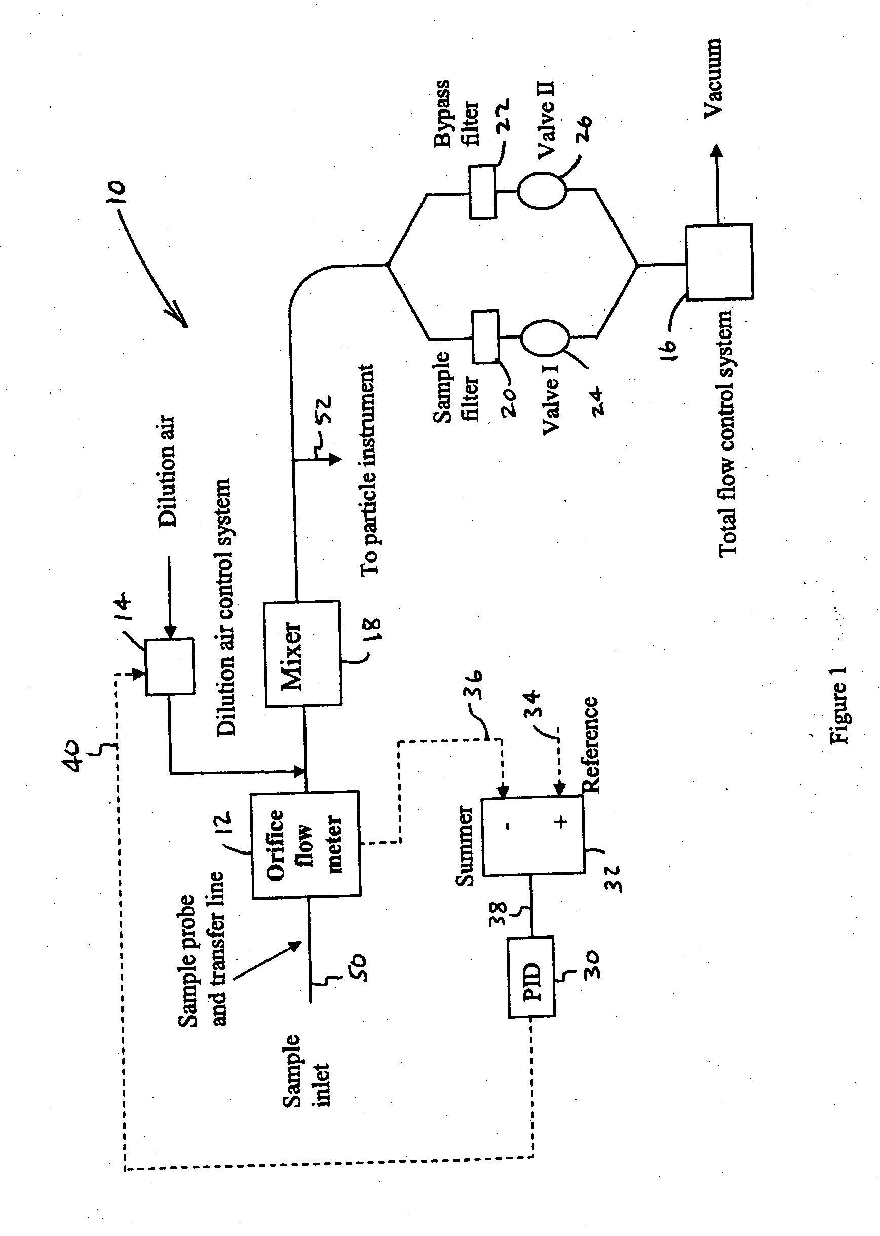
[0021] In FIG. 1, the sampler is generally indicated at 10. Sampler 10 includes orifice flow meter 12, dilution air control system 14, total flow control system 16, and mixer 18. Sampler 10 further includes sample filter 20 and associated valve 24, as well as bypass filter 22 and associated valve 26. In this preferred embodiment, sampler 10 further includes proporational, integral, derivative (PID) controller 30. Summer 32 receives reference signal 34 at its positive input. Summer 32 receives feedback signal 36 from orifice flow meter 12 at its negative input. The error signal 38 is processed by PID controller 30 to produce signal 40, which drives dilution air control system 14.

[0022] With continuing reference to FIG. 1, the sample flows into sampler 10 through the sample probe and transfer line 50. The flow rate of the sample flow is measured in orifice flow meter 12. The sample flow mixes with dilution air in mixer 18. Mixer 18 may be a tunnel or cyclone or other mixing device. I...


PUM


Abstract

A partial flow sampling system includes a system inlet for receiving an exhaust sample flow from a sample inlet probe and transfer line. The system further includes a dilution air control system for controlling a dilution air flow rate, and a mixer. The mixer receives and mixes the exhaust sample flow and the dilution air flow to produce a mixture flow. A total flow control system controls the mixture flow rate. An orifice flow meter installed at the system inlet measures the exhaust sample flow rate in. real-time. This provides accurate sample flow measurements over a wide range of dilution ratios and sample ratios.

Description

BACKGROUND OF THE INVENTION [0001] 1. Field of the Invention [0002] The invention relates to a sampler for taking a sample from raw engine or vehicle exhaust, or from a primary dilution system. [0003] 2. Background Art [0004] The United States Environmental Protection Agency (EPA) defines engine emitted particulate matter (PM) as material collected by filtration of diluted exhaust with a filter temperature of not more than 52° C. A large number of dilution systems have been developed to meet this criterion. [0005] The constant volume sampler (CVS) is a full flow dilution tunnel. The CVS takes all engine exhaust and dilutes the exhaust proportionally. The dilution process in the CVS is straightforward, and is very accurate for gaseous and PM measurement. However, the CVS is expensive, large in size, and not portable. As well, a specific CVS may only be used for a particular range of engine sizes. [0006] Another approach to diluting engine exhaust is provided by the partial flow sampl...

Claims


Application Information

Patent Timeline
Patent Type & Authority Applications(United States)
IPC IPC(8): G01M15/00
CPCG01M15/102G01N2001/2264G01N33/0018G01N1/2252
Inventor WEI, QIANGASANO, ICHIRO
Owner HORIBA LTD
Why Eureka
Try Eureka