Diesel exhaust filter construction

a technology of exhaust filter and diesel, which is applied in the direction of filtration separation, separation process, lighting and heating apparatus, etc., can solve the problems of increasing complexity of devices, both in terms of components and functions, and achieve the effects of reducing the total number of parts, simplifying their construction, and efficient us

Inactive Publication Date: 2009-11-03
BENTELER AUTOMOTIVE CORP
View PDF46 Cites 26 Cited by
  • Summary
  • Abstract
  • Description
  • Claims
  • Application Information

AI Technical Summary

Benefits of technology

[0008]In yet another aspect of the present invention, an exhaust filter assembly for filtering exhaust gases from a diesel engine includes a filter block adapted to filter exhaust gases from a diesel engine. A jacket is formed around the filter block, the jacket defining an inlet and outlet for flow of the exhaust gases into and out of the filter block, respectively. A shield subassembly is positioned between the filter block and the jacket, the shield subassembly including shield members with embossments that support the shield members away from the jacket to thus form an air gap that extends substantially fully around a circumference of the filter block and along at least a majority of a length of the filter block. Basalt wool insulation is positioned in the air gap and takes up some space in the air gap to further reduce surface temperature.
[0010]Another object of the present invention is to provide a diesel filter element that integrates several functions, so as to reduce the total number of parts in the assembly, simplify their construction, properly channel exhaust gas flow, form an internal heat shield, and support an associated filter block in the jacket in a manner which accommodates free thermal expansion of the core.
[0011]Yet another object of the present invention is to provide a diesel filter element that is efficient in use, economical to manufacture, capable of long operating life, and particularly well adapted for the proposed use.

Problems solved by technology

These devices are becoming increasingly complex, both in terms of components and function.

Method used


Image

  • Diesel exhaust filter construction
  • Diesel exhaust filter construction
  • Diesel exhaust filter construction

Examples


Embodiment Construction

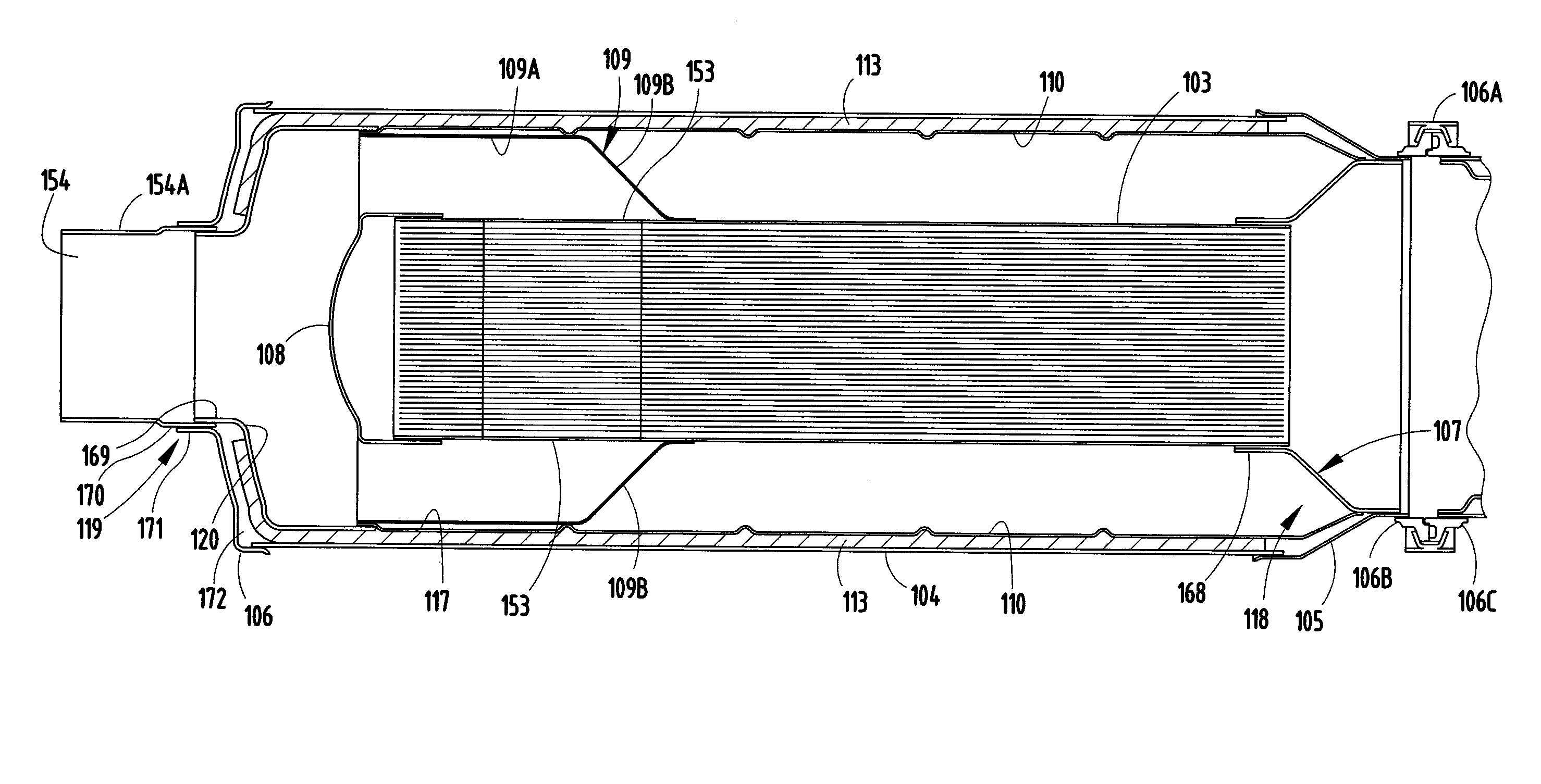
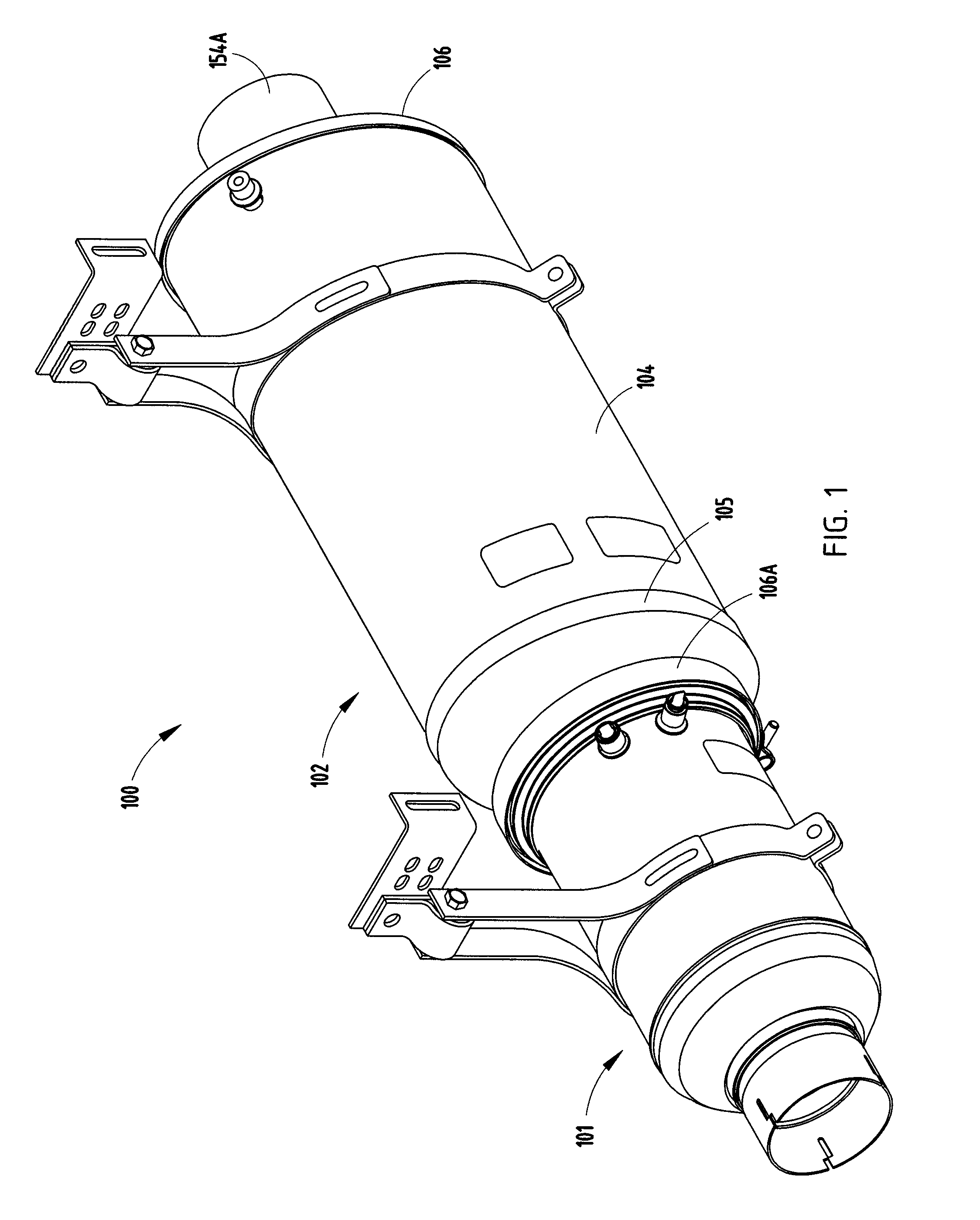
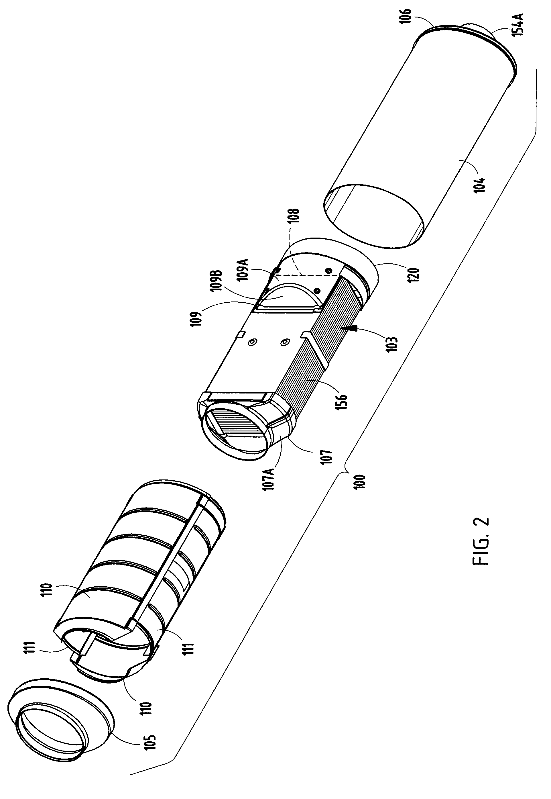
[0019]A diesel exhaust device 100 (FIGS. 1-3) includes a DOC subassembly 101 with diesel oxidation catalyst (DOC) for chemically treating diesel exhaust and a diesel particulate filter (DPF) subassembly 102 adapted to filter particulate from diesel exhaust. The subassemblies use known technologies to accomplish their purposes such that their physical and chemical properties, and also their operating systems, do not need to be described in detail for a person of ordinary skill to understand the present invention. However, the present DPF subassembly 102 is particularly and inventively constructed to provide advantages as noted below.

[0020]The present DPF subassembly 102 (FIG. 2) includes a rectangular particulate filter block 103 comprising a plurality of closely-spaced parallel particulate-filtering sintered metal plates sandwiched between a pair of carrier plates, an elongated non-rectangular jacket 104 with oval cross section, and components forming a support structure for support...


PUM

PropertyMeasurementUnit
lengthaaaaaaaaaa
surface temperatureaaaaaaaaaa
resistanceaaaaaaaaaa

Abstract

A diesel exhaust filter construction includes a rectangular filter block, an elongated non-rectangular jacket with oval cross section, and support structure supporting the filter block in a center of the jacket. The support structure includes shielding components forming an insulating air gap with the jacket around the filter block (including a double-layered air gap in “hot” areas), and further includes support structure slidably supporting one end of the filter block to accommodate dissimilar thermal expansion. The structure further includes baffling components with angled surfaces directing input exhaust gases along efficient flow paths from an inlet cone into front, rear, and opposite sides of the filter block and further directing output exhaust gases from top and bottom sides of the filter block toward a longitudinally-centered outlet cone. Some components are identical is shape and size for use in different locations on the construction, thus simplifying tooling.

Description

CROSS REFERENCE TO RELATED APPLICATION[0001]This application claims benefit under 35 U.S.C. § 119(e) of provisional application Ser. No. 60 / 832,123, filed Jul. 20, 2006, entitled SUPPORT STRUCTURE FOR DIESEL EXHAUST FILTER ELEMENT.BACKGROUND[0002]The present invention relates to diesel exhaust treatment devices for internal combustion engines and the like, and in particular relates to a diesel exhaust filter construction for reducing undesirable emissions, for reducing assembly and component cost, and for increasing operating efficiency of the device.[0003]Modern diesel engines are provided with diesel exhaust treatment devices to reduce environmentally-unfriendly gaseous emissions and particulate emissions. These devices are becoming increasingly complex, both in terms of components and function. An improved diesel exhaust filter construction is desired that uses less components and less costly components, that uses components facilitating assembly and also long term durability, an...

Claims


Application Information

Patent Timeline
Patent Type & Authority Patents(United States)
IPC IPC(8): B01D39/00B01D39/06B01D39/14B01D50/00B01D53/34F01N3/08F01N3/10F01N13/14
CPCF01N3/0211F01N13/14Y02T10/20F01N2260/10F01N2330/14F01N2240/20Y02T10/12
Inventor HILL, JR., FREDERICK B.REMENAR, MICHAEL J.
Owner BENTELER AUTOMOTIVE CORP
Why Eureka
Try Eureka